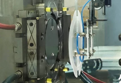
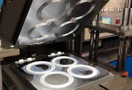
Protolis has recently invested in a new 3D scanner, further expanding our in-house dimensional inspection capabilities. We combine 3D scanning with targeted measurements using appropriate calibrated equipment.
3D scanning allows us to assess overall geometry and larger external dimensions against the nominal CAD model, while complementary measurements are used to check selected small features and dimensions with tighter tolerances. Together, these methods provide a more comprehensive basis for evaluating manufactured parts.
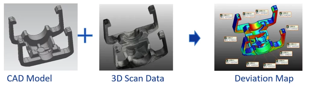
From manufactured part to CAD comparison
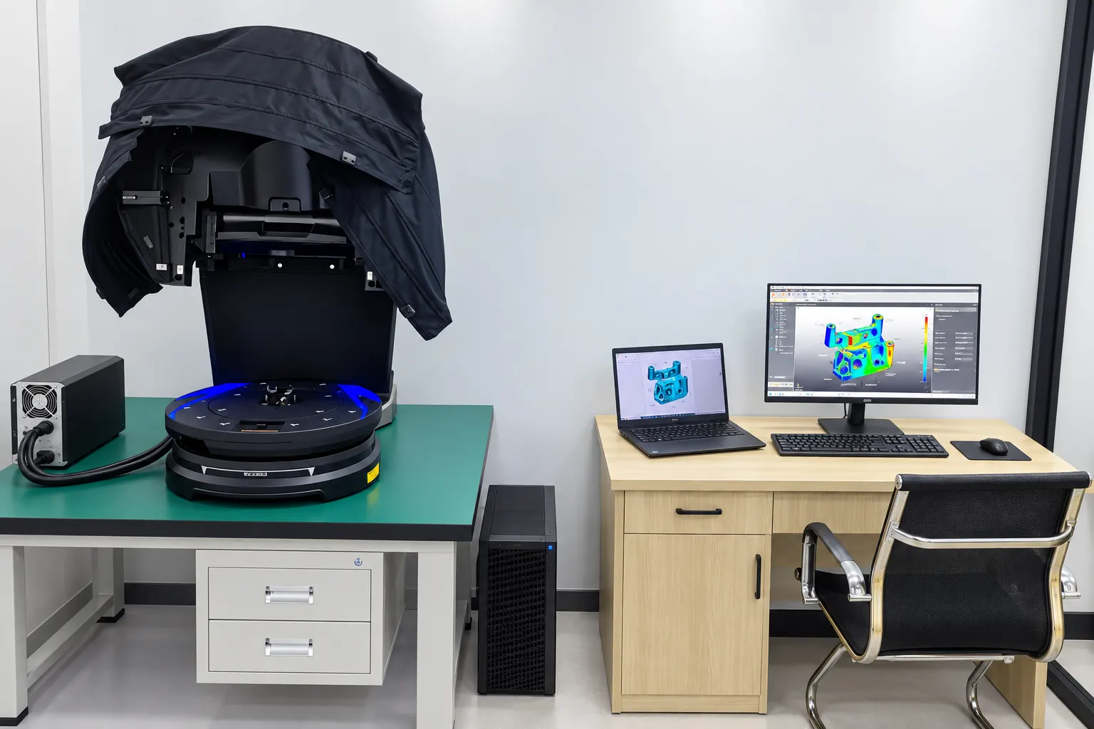
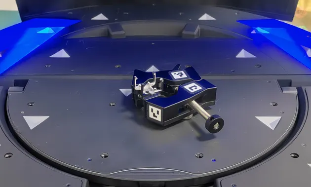
We recently purchased a KEYENCE VL-800 Series 3D Scanner CMM to strengthen our in-house dimensional inspection capabilities. The system captures the accessible external geometry of a manufactured part and enables the scan data to be compared with the nominal 3D CAD model.
Once the scan has been aligned with the CAD model, the software displays surface deviations as a colour map. This makes it easier to identify areas that differ from the intended geometry and determine whether the deviations are localised or extend across a larger surface.
For a housing, bracket or curved component, this broader view can help guide investigations into shape or assembly issues. It also provides project and engineering teams with a common visual reference when discussing the next steps.
How to read a colour deviation map
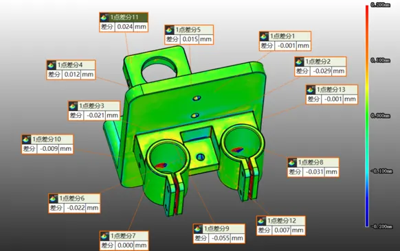
The colours represent positive and negative surface deviations relative to the aligned CAD model, according to the scale shown in the legend. The meaning of each colour therefore depends on the scale selected for the specific report.
For example, the report shown in our inspection presentation uses a scale ranging from -0.20 mm to +0.20 mm. This represents the displayed deviation range for that particular example. It does not define a tolerance of ±0.20 mm for every feature, nor does it represent the accuracy of the scanner.
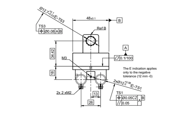
Surface colour comparisons and dimensional measurements answer different questions. A predominantly green colour map does not, on its own, confirm that every hole diameter, centre distance or geometric tolerance complies with the drawing. Conformity must be assessed against the relevant requirements using an appropriate measurement method.
Why we combine 3D scanning with conventional measurement
The inspection method must be appropriate for both the geometry being assessed and the required tolerance. Our combined approach uses 3D scanning to evaluate the overall external shape, followed by suitable calibrated measuring equipment to inspect selected features and tighter-tolerance dimensions.
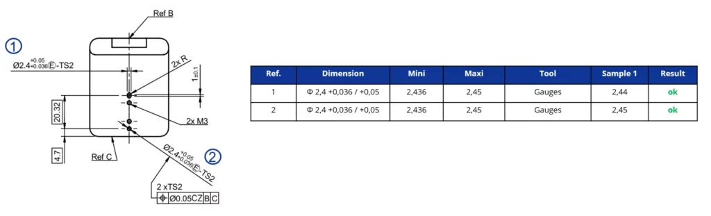
The sample report illustrates this with two holes specified as Ø2.4 mm, with deviations of +0.036 mm and +0.050 mm. Their allowable diameter range is therefore 2.436 mm to 2.450 mm, giving a total tolerance band of just 0.014 mm. These features are checked separately using gauges alongside the 3D scan comparison.
This example demonstrates why a single colour scale cannot be used as the acceptance criterion for an entire part. Overall surface comparison and the inspection of individual features must be evaluated together.
Define the inspection scope before production
A useful dimensional inspection starts with clearly defined reference information. Send us your latest 3D CAD model and corresponding 2D drawing, and identify the dimensions that are most critical to assembly or function. Applicable tolerances and datum references should also be provided so that the inspection results can be interpreted in the correct context.
Scan alignment is equally important, as it determines how the measured part is positioned relative to the CAD model. Where a drawing specifies functional datums, these need to be considered when planning the inspection. The report should clearly state the basis used for the comparison.
Before production, discuss the required inspection scope with your Protolis project contact and agree which features need to be checked, the required sampling plan and the level of reporting detail. This helps ensure that the inspection focuses on the questions your team needs to answer.
Clear results to support your next decision
A combined inspection report can include the CAD comparison, the corresponding deviation scale and a table of selected dimensional measurements. For individual dimensions, information such as the nominal value, allowable limits, measurement method and measured result provides the basis needed to assess conformity.
For prototyping and low-volume manufacturing, these results can support decisions on part acceptance, further investigation or potential adjustments. Dimensional inspection is only one part of the overall assessment, and functional testing under the intended application conditions may still be required.
Have a project involving complex geometry or critical assembly dimensions? Share your CAD files, drawings and inspection priorities with Protolis. Our team can discuss a suitable combination of 3D scanning and targeted dimensional measurements for your parts.