The Protolis guide to CNC machining
CNC machining is a cornerstone in modern manufacturing, a field constantly evolving with technology and innovation. Whether you’re a beginner or seasoned in the field, this guide will deepen your understanding of CNC, from its foundational concepts to its changing applications.
Method Type
Jump to current chapter
Current Chapter
- The basics of CNC machining
- What is CNC?
- Types of CNC machining: 3-axis to 5-axis
- CNC machining operations
- Main steps of the CNC machining process
- History of CNC
- What are the advantages of CNC?
- What are the limitations of CNC?
- Suitable materials for CNC machining
- How to choose the most suitable material for CNC
- Finishes for CNC machined parts
- Main applications of CNC parts
- Best design pratices for CNC machining
- Understand the tool access of your part
- Optimize radius and edge features
- Pockets and cavities
- Inadequate wall thickness
- Design and make holes with standard sizes
- Internal threads
- External threads
- Machined text
- Undercuts
- Choose the right tolerances
- Choose the right clearances and avoid errors
- Cost optimisations for CNC machining
- Conclusion
The basics of CNC machining
We’ll explore the historical journey of CNC machining, its diverse uses, and the advantages it offers. We’ll also explore its limitations and offer insights into design considerations and cost factors. Get ready to embark on an informative journey that will spark your curiosity and broaden your knowledge of CNC machining.
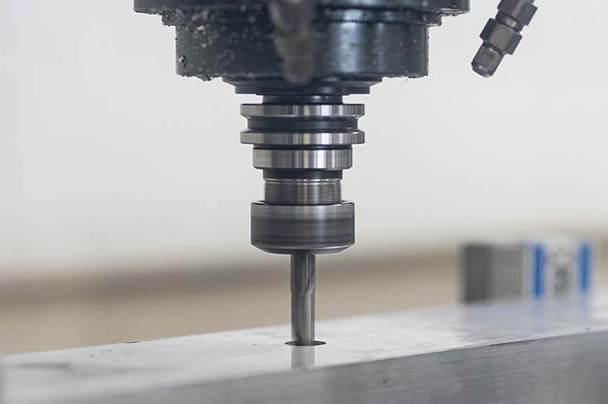
What is CNC?

CNC, or computer numerical control, represents a subtractive machining process. It operates by precisely removing material from a workpiece, guided by computer programming. This method employs cutting tools for shaping materials into intricate parts with exceptional accuracy. Its precision and efficiency make it indispensable in modern manufacturing. We focus here on CNC’s cutting tool applications, showcasing its pivotal role in creating complex components with remarkable precision.
Types of CNC machining: 3-axis to 5-axis
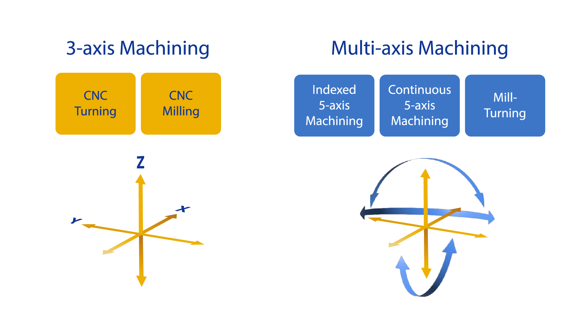
CNC machining varies notably with the number of axes, each suited for specific manufacturing needs. 3-axis CNC operates in three directions, ideal for 2D and 2.5D geometries but limited in creating angled features. In contrast, 4-axis CNC introduces an additional rotational axis, enhancing the ability to machine complex parts without fixture changes.
Meanwhile, 5-axis CNC machining brings two more rotational axes, simultaneously allowing manipulation from five sides. It offers two modes: ‘indexing and ‘continuous’. This advanced capability is crucial for intricate, high-quality finishes in complex components, and is widely used in industries like automotive and aerospace, balancing complicated design possibilities with efficient production.
CNC machining operations
CNC machining operations encompass various processes, each tailored for specific manufacturing outcomes.
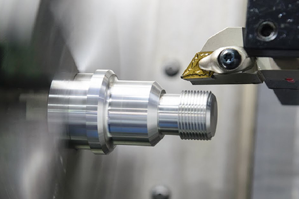
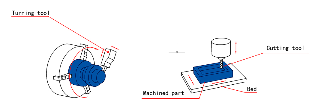
CNC turning
This process involves a stationary cutting tool and a rotating workpiece, and is predominantly used for cylindrical parts. In turning, the material is symmetrically removed from the material block, a technique frequently employed in creating turbine cylindrical holes.
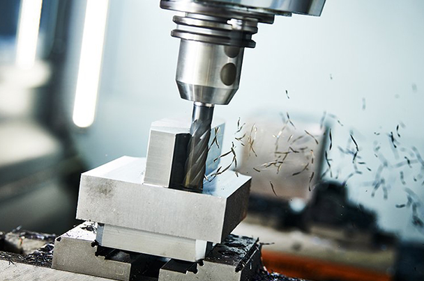
CNC milling
Milling uses a stationary workpiece and a high-speed rotating cutting tool. CNC mills offer diverse axes options, catering to various needs. The tool shapes vary, facilitating different milling types like end, face, and slab milling.
CNC drilling
This process employs a drill bit to create precise holes in the workpiece. Common in CNC setups, drilling machines are often combined with other processes. While their hole diameter range is limited, they’re essential for tasks like screw hole punching or aesthetic enhancements.
While these operations are among the most commonly used in CNC machining, several other techniques have unique capabilities and applications. They include CNC routing, grinding, honing, lapping, broaching, laser cutting, water jet machining, and EDM (electrical discharge machining).
Main steps of the CNC machining process
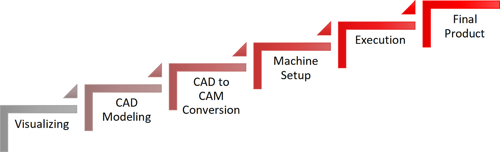
The CNC machining process is systematic, ensuring precision and efficiency at each stage.
Stage 1: Blueprint development
Initially, professionals like designers and engineers draft blueprints. These blueprints outline the part’s features and applications, serving as a foundational guide for the upcoming stages.
Stage 2: CAD modeling
The blueprint evolves into a digital model using computer-aided design (CAD) software. This model provides a detailed representation, including dimensions, wall thickness, and depths of any cavities.
Stage 3: CAD to CAM conversion
CNC machines require a specific format to interpret designs. Thus, CAD models are converted into a cComputer-aided manufacturing (CAM) format, which is readable by CNC machines. Various CAM software tools like Mastercam, PowerMILL, and CAMWorks facilitate this conversion.
Stage 4: Machine setup
Before the actual machining, the machine needs to be meticulously configured. This involves transferring the CAM file to the machine, adjusting settings, and securely mounting the object on the work table. This stage is crucial for ensuring accuracy and safety.
Stage 5: Executing the program
The operator then initiates the program, prompting the machine to start its precise tool movements. The program runs until completion or is stopped in case of errors or emergencies.
Stage 6: Post-machining steps
Finally, the machined part is removed for inspection. Quality checks are conducted, and the piece may be forwarded for secondary processes, such as finishing, if needed.
Each stage in the CNC machining process plays a vital role in ensuring the final product meets both design and quality standards.
History of CNC

CNC’s history dates back to the late 1940s with John T. Parsons’ development of the first numerical control (NC) machine, operated via punch cards. This breakthrough laid the foundation for CNC technology. In 1952, a team at MIT, including J.F. Reintjes, introduced the prototype of the first CNC milling machine. Collaborating with MIT, Richard Kregg played a pivotal role in commercializing this technology with the Cincinnati Milacron Hydrotel milling machine, marking a significant milestone in CNC manufacturing.
Where was it created?
The groundbreaking development of CNC machines originated in the United States, primarily at MIT. The collaborative efforts between MIT and Cincinnati companies facilitated the birth of the first commercial CNC machines, revolutionizing manufacturing processes.
Evolution of CNC machining
The evolution of CNC machining is a story of technological progress and innovation shaped by the needs of the times.
1952 – 1958: The inception of CNC machining
In response to the demands of the Cold War era for more efficient production, 1952 saw the creation of the first CNC milling machine, the Cincinnati Milacron Hydrotel. This was a collaborative effort by Richard Kegg and MIT. By 1958, this innovation was solidified with Kegg’s patent for a motor-controlled apparatus for positioning machine tools, marking a pivotal moment in CNC history.
1967 – 1972: Global recognition and advancements
As the 1970s approached, CNC machining gained global recognition, bolstered by the development of computer-aided design (CAD) and computer-aided manufacturing (CAM) in 1972. This period marked a significant leap in CNC technology, integrating digital design and manufacturing processes, although they weren’t yet standard in manufacturing.
1976 – 1989: Standardization and 3D capabilities
Significant advancements marked the late 1970s and 1980s. In 1976, 3D CAD and CAM were introduced into CNC machining, enhancing its capabilities. By 1989, these technologies had become the industry standard, revolutionizing the CNC machining process and paving the way for more complex and precise manufacturing techniques.
Modern CNC: Versatility and novel methods
Today’s CNC machines epitomize electronic control and versatility, handling various materials with predictable outcomes. This era has also seen the advent of new machining methods like electron beam machining (EBM), electrical discharge machining (EDM), and plasma machining, which are chosen based on material properties and production needs.
What are the advantages of CNC?
CNC machining stands out for its blend of efficiency, precision, and versatility, making it a go-to choice in modern manufacturing. Some of its significant benefits are as follows:
CNC machines are renowned for their exceptional accuracy. They meticulously follow digital designs, ensuring parts are produced with high precision, which is crucial for intricate and detailed components.
Speed is a hallmark of CNC machining. It quickly translates digital designs into physical parts, significantly reducing production time compared to traditional methods.
One of CNC’s strengths is its ability to produce anything from a single piece to hundreds with consistent quality. This repeatability makes it a cost-effective solution, especially for medium-scale production runs.
These technological machines excel in crafting complex shapes that would be challenging or impossible to achieve with manual processes, offering greater design flexibility.
Another advantage is versatility in material compatibility. CNC machines adeptly handle various materials, including metals, plastics, composites, and wood, broadening their application across different industries. This adaptability ensures that CNC machining remains a crucial tool in the manufacturing arsenal.
What are the limitations of CNC?
While CNC machining is a valuable asset in manufacturing, it’s essential to recognize its limitations.
The cost of CNC machining can escalate with increasing quality and complexity. Advanced projects demanding high precision and intricate design can significantly raise expenses.
CNC’s subtractive nature often leads to material wastage. The process involves removing material to shape the final product, resulting in excess scrap, especially in more complex designs.
CNC machining faces constraints if designs aren’t adapted to their capabilities. Challenges arise with undercuts or requirements for 5-axis machining, limiting design flexibility.
It also lacks the economy of scale for mass production. It i’s less cost-effective than other methods when producing large quantities, as the time and resource investment per unit remains constant.
Size is a critical factor in developing CNC machined parts. Larger pieces might need to be divided into smaller segments, affecting the assembly process. Conversely, very small or fragile parts pose challenges in machining without damage. Alternative manufacturing technologies might be more suitable in these cases.
Suitable materials for CNC machining
CNC machining accommodates a broad range of materials which you can select according to the specific needs of your project. Metals and plastics are the most commonly used CNC-machined materials. Both materials offer unique properties and advantages.
Metals
Metals are preferred for high strength, hardness, and thermal resistance applications.
- Aluminum is popular due to its versatility, lightweightness, and excellent machinability. Aluminum 6061 is mainly used for general purposes, whereas aluminum 7075 is suitable for aerospace applications where weight reduction is critical.
- Stainless steel, including alloys like 304 and 316, is valued for its strength, ductility, and corrosion resistance. Its high strength makes it suitable for several automotive, military, and engine components applications.
- Brass is another frequently used CNC material, prized for its excellent machinability, corrosion resistance, and good mechanical properties. This material is ideal for manufacturing functional parts.
Plastics
Plastics are lightweight and are often chosen for their chemical resistance and electrical insulation capabilities.
- ABS is a commonly used plastic in CNC machining due to its unmatched mechanical properties and impact strength. It is ideal for developing prototypes and lightweight parts.
- Nylon, mainly nylon 6 and nylon 66, is used for engineering applications due to its excellent resistance against chemicals and abrasion.
- Polycarbonate (PC) offers high toughness and impact strength, making it suitable for applications like fluidic devices or automotive glazing. POM (Delrin) is preferred for parts requiring high precision, stiffness, and low friction.
- PTFE (Teflon) is notable for its exceptional chemical and thermal resistance and is often used in high-temperature applications or as an electrical insulator.
Other materials
Beyond metals and plastics, CNC machining also works with materials like wood and composites. They offer versatility for both aesthetic and structural applications across various industries.
Check material availability
For an in-depth exploration of the diverse range of materials suitable for CNC machining, we encourage you to visit our material availability page. You’ll find detailed insights into each material’s properties to help you make informed decisions for your specific CNC needs.
How to choose the most suitable material for CNC
Suitable material selection is essential to ensure the functionality and cost-effectiveness of the final product. Here are some key factors to consider:
Different materials react uniquely to various machining conditions, such as cutting speed, tool material, and coolant. The environment includes factors like temperature, humidity, and the presence of contaminants. Select materials that are compatible with these conditions to improve productivity and maintain quality.
Heavier parts require more material and powerful CNC machines, increasing costs and production time. Opting for materials like aluminum or magnesium can reduce weight and lower costs. Weight also affects the final product’s performance, especially in sectors like aerospace and automotive.
Materials must withstand high temperatures without significant deformation or damage. Good heat resistance allows faster cutting speeds and deeper cuts, shortening machining times and reducing tool wear. Materials like aluminum and copper are suitable for heat sinks, while stainless steel and titanium are ideal for high-temperature applications.
Materials with high electrical conductivity, like copper and aluminum, effectively dissipate heat, preventing warping or deformation. Non-magnetic materials like titanium and stainless steel produce cleaner cuts as magnetic fields don’t affect them.
The hardness of the material affects machinability, tool wear, and surface finish. Too-hard materials can be challenging to cut, resulting in poor dimensional accuracy, while too-soft materials may deform undercutting force.
The surface finish impacts the part’s performance and appearance. A smooth surface finish reduces friction, improving performance and lifespan. The material should also be visually appealing and capable of being polished or painted if aesthetics are a significant factor, especially in high-end retail or luxury automotive and aerospace industries.
Consider if the part will be used indoors or outdoors. Materials like aluminum and plastics are preferable in wet environments to prevent rusting. Design specifications like stress load, tolerance, and types of fastening should also influence material choice.
Material and machining costs are critical considerations. While high-grade metals may be costly, plastics or composites can be more affordable. Choosing the appropriate materials for your project that are affordable to machine can keep overall production costs down while ensuring that the finished product is durable and of high quality.
Rating CNC materials
| Material Type | Machining Environment | Part Weight | Heat Resistance | Electrical Conductivity | Hardness | Surface Finish |
|---|---|---|---|---|---|---|
| Metals | ||||||
| Aluminum | Excellent | Excellent | Good | Excellent | Good | Excellent |
| Stainless Steel | Good | Good | Excellent | Poor | Excellent | Good |
| Brass | Good | Good | Good | Good | Good | Excellent |
| Titanium | Good | Poor | Excellent | Poor | Excellent | Good |
| Plastics | ||||||
| ABS | Good | Excellent | Good | Excellent | Good | Good |
| Nylon | Good | Excellent | Good | Excellent | Good | Good |
| Polycarbonate | Good | Excellent | Good | Excellent | Good | Good |
| POM (Delrin) | Excellent | Excellent | Good | Excellent | Excellent | Excellent |
| PTFE (Teflon) | Good | Excellent | Excellent | Poor | Good | Good |
Note: The ratings in this chart are generalized based on typical properties and applications of these materials. Specific applications may result in different performance levels. Consult our experts for precise material selection.
Finishes for CNC machined parts
Choosing the right finish for CNC machined parts ensures the desired aesthetics, functionality, and durability. Here’s an overview of the most common finishes:
An ”as machined” finish leaves the part with visible tool marks and a rough texture, typically around 3.2 μm surface roughness. It offers tight dimensional tolerances at an affordable cost due to the lack of post-processing. Ideal for projects where dimensional integrity outweighs aesthetics, this finish is not highly protective against nicking and scratching.
Polishing, particularly electropolishing, is applied to steel or stainless steel to achieve a super fine or mirror finish. It uses an electric current and chemical bath to dissolve a controlled layer of the base material. Parameters like electrolyte composition and temperature can be adjusted for different polish levels. It’s a cost-effective and faster alternative to manual polishing.
Anodizing applies a protective oxide layer on aluminum parts, enhancing corrosion, wear, and scratch resistance. It involves immersing the part in an electrolyte solution and using an electric current to form a protective oxide layer.
This process not only enhances corrosion and wear resistance but also imparts a coarse, grainy surface finish to the metal. It’s particularly effective for trapping dye in the oxide layer, offering a near-permanent color. Anodizing types vary:
- Type I: Uses chromic acid, creating a thinner layer suitable for applications where dimensional changes are a concern.
- Type II: Also known as decorative anodizing, uses sulfuric acid to produce a thicker layer (up to 25μm), available in various colors.
- Type III: Known as hard coat anodizing, forms the thickest oxide layer (25 to 150μm) using a higher voltage current and controlled temperature, ideal for high-performance applications.
Each type of anodizing offers distinct advantages and is chosen based on the specific requirements of the CNC machined parts.
This coating is suitable for steel and stainless steel, offering corrosion and abrasion resistance and improved lubricity. Applied through a high-temperature chemical bath, black oxide coating provides a smooth, matte finish without significantly altering dimensions. However, it’s less suitable for high-stress applications due to abrasion susceptibility.
Bead blasting uses pressurized glass or ceramic beads to create a consistent, matte finish on metal surfaces. It effectively removes imperfections and cleans the surface for subsequent processes. While offering a uniform appearance, bead blasting can affect dimensional accuracy and is typically reserved for higher-value projects due to its cost.
Powder coating, commonly used on steel, stainless steel, and aluminum, involves electrostatically applying powdered paint and curing it at high temperatures. It offers a durable, thick, uniform coating in various colors and gloss levels. However, it alters part dimensions and has low electrical conductivity, requiring careful consideration of tolerances and roughness.
Each of these finishes has unique advantages and suitability, depending on the specific requirements of your CNC machined parts. The selection should be based on factors like material type, intended use, environmental exposure, and aesthetic preferences.
Check finish availability
Visit our finish availability page to get a comprehensive overview of the finishing options we offer for CNC machined parts.
Main applications of CNC parts
CNC machining, a vital technology in modern manufacturing, excels in creating precise and complex parts across various industries.

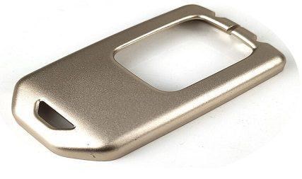
Electronics
CNC machining significantly impacts the consumer electronics sector. For instance, laptops and smartphones’ sleek metal alloy casings are typically crafted using CNC milling machines. This technique is not limited to exterior design but extends to internal components, ensuring functional and aesthetic excellence.
Common applications: PCBs, device housings, manufacturing jigs, heat sinks, etc.

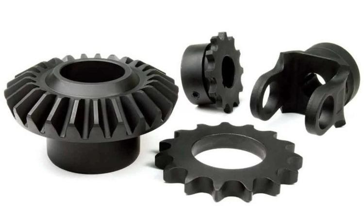
Automotive
CNC machining is essential in the automotive industry, from R&D prototyping to large-scale production. It crafts a range of components, from large engine blocks to smaller gears and panels. The versatility of CNC milling and lathe machines in the automotive sector allows for the production of complex parts with precision.
Common applications: Gearboxes, engine components, axles, valves, etc.

Robotics
The burgeoning field of robotics and automation heavily relies on CNC machining for part production. The precision and customization CNC offers are crucial for creating components with specific functionalities.
Common applications: Robotic arms, end effectors, sensors, specialized fixtures, etc.

Aerospace
CNC machining is indispensable in aerospace due to the high precision and accuracy required for every component. Stringent requirements for flatness, roundness, and cylindricity, often with tolerances as small as 0.00004 inches, are standard in this industry.
Common applications: Landing gear parts, titanium shrouds, airfoil sections, bushings, etc.

Medical
The medical industry relies heavily on CNC machining to produce high-precision, custom-made components. Working with medically safe materials and maintaining strict tolerances is crucial for medical devices and equipment. CNC technology aids in the creation of components essential for patient care and medical research.
Common applications: MRI components, surgical implants, orthotic devices, etc.

Rapid prototyping
Rapid prototyping is a key application of CNC machining, enabling the quick and efficient creation of prototypes for testing and development. CNC machining facilitates the rapid production of prototypes with high accuracy, allowing for effective testing and iteration.
Common applications: Concept models, functional prototypes, assembly mock-ups, etc.

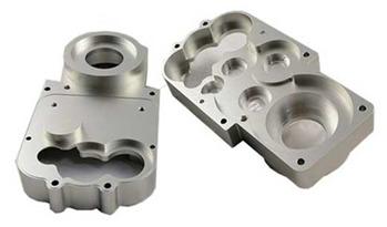
Plastic injection mold
CNC machining is extensively used in producing molds for plastic injection molding. This process is vital in manufacturing various plastic components used in multiple industries. Molds manufactured by CNC ensure precision, durability, and capability to produce high-quality plastic parts.
Common applications: Two-shot injection molds, thin-wall injection molds, die casting molds, etc.
These applications demonstrate the versatility and importance of CNC machining across different sectors, highlighting its role in advancing technology and manufacturing practices.
Best design pratices for CNC machining
Discover key CNC machining design principles to enable efficient, cost-effective production and consistently high-quality components. Optimize your designs for manufacturability.
Understand the tool access of your part
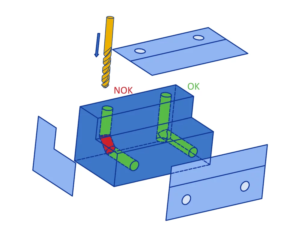
This is our first recommendation, as tool access is one of the main design limitations in CNC machining. In order to reach all surfaces of the part, the workpiece may need to be rotated several times.
Each time the workpiece is rotated, the machine must be recalibrated, and a new coordinate system must be set up, which increases costs and reduces accuracy. While using a 5-axis machine can help minimize accuracy problems, it is more expensive than a 3-axis CNC machine.
Therefore, it is important to carefully consider the total number of machine setups required to machine your part. Additionally, remember that surfaces that the cutting tool cannot reach cannot be CNC machined. This limits the possibility of creating parts with internal ‘hidden’ geometries and also restricts the maximum depth of undercuts.
Optimize radius and edge features
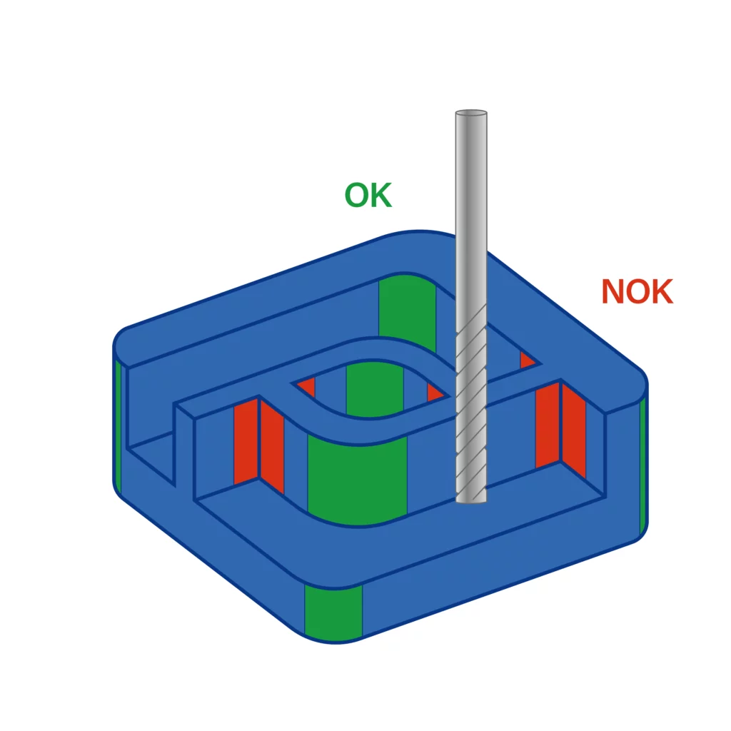
Most CNC milling and cutting tools are cylindrical in shape, which naturally creates a radius in the corners of a pocket during edge cutting. Since these tools cannot produce sharp right-angled edges, it is essential to incorporate a radius into internal edges during the design phase. To reduce tool wear and optimize performance, we recommend adding a radius that is **130% of the milling tool’s radius**. This not only decreases stress on the tool but also allows for higher cutting speeds. Additionally, using a consistent radius across all internal edges can eliminate the need for tool changes, simplifying the process and improving efficiency.
Although smaller radii can be achieved with tools of smaller diameters, sharp corners cannot be entirely removed. These smaller tools require multiple passes at slower speeds, as they remove material less efficiently than larger tools. This leads to increased machining time and cost.
Our recommendations for radius design:
- Inner radius: aim for the largest possible inner radius for pocket shapes. This simplifies manufacturing, enhances structural strength, and reduces costs.
- No inner radius: if the design requires sharp inner edges for assembly purposes, metal parts will be created using EDM machining, while plastic parts will be manually machined to achieve the desired shape.
- Outer radius: boundary edges with an outer radius can be easily machined using standard CNC tools.
Pockets and cavities
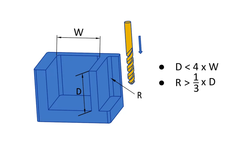
Deep pockets and cavities can lead to manufacturing challenges, such as tool deflection, difficulty with chip removal, and tool breakage, all of which can significantly increase machining time and costs.
To mitigate these issues, we recommend:
- Limiting cavity depth to no more than four times the width.
- Limiting cavity depth to two to three times the tool diameter.
If a deeper cavity is required, increasing corner radii allows a bigger tool to follow a circular path rather than a 90-degree angle. This reduces tool strain, improves surface finish, and can slightly reduce cycle times.
Smaller radii can be achieved by using smaller cutters, either throughout the entire program or as a secondary tool pass after roughing. However, this will increase both time and cost.
Inadequate wall thickness
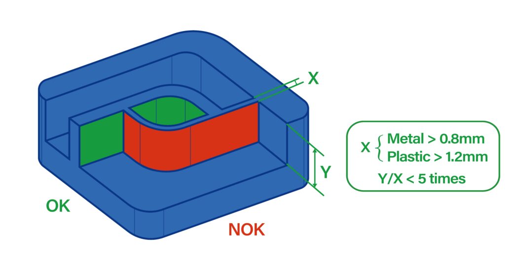
One common design issue is insufficient wall thickness, which can compromise material stiffness and precision while making parts more susceptible to vibrations during machining. To address this, here are three recommendations:
- Metal parts: thin walls should have a thickness between 0.5-0.8 mm (0.020-0.031 inch).
- Plastic parts: thin walls should have a thickness between 0.8-1.2 mm (0.031-0.047 inch).
- Height of thin walls: keep the height of thin walls as low as possible, ideally no greater than 5 times the wall thickness.
Design and make holes with standard sizes
Holes are common features in CNC-machined parts, and designers should consider the following when designing holes:
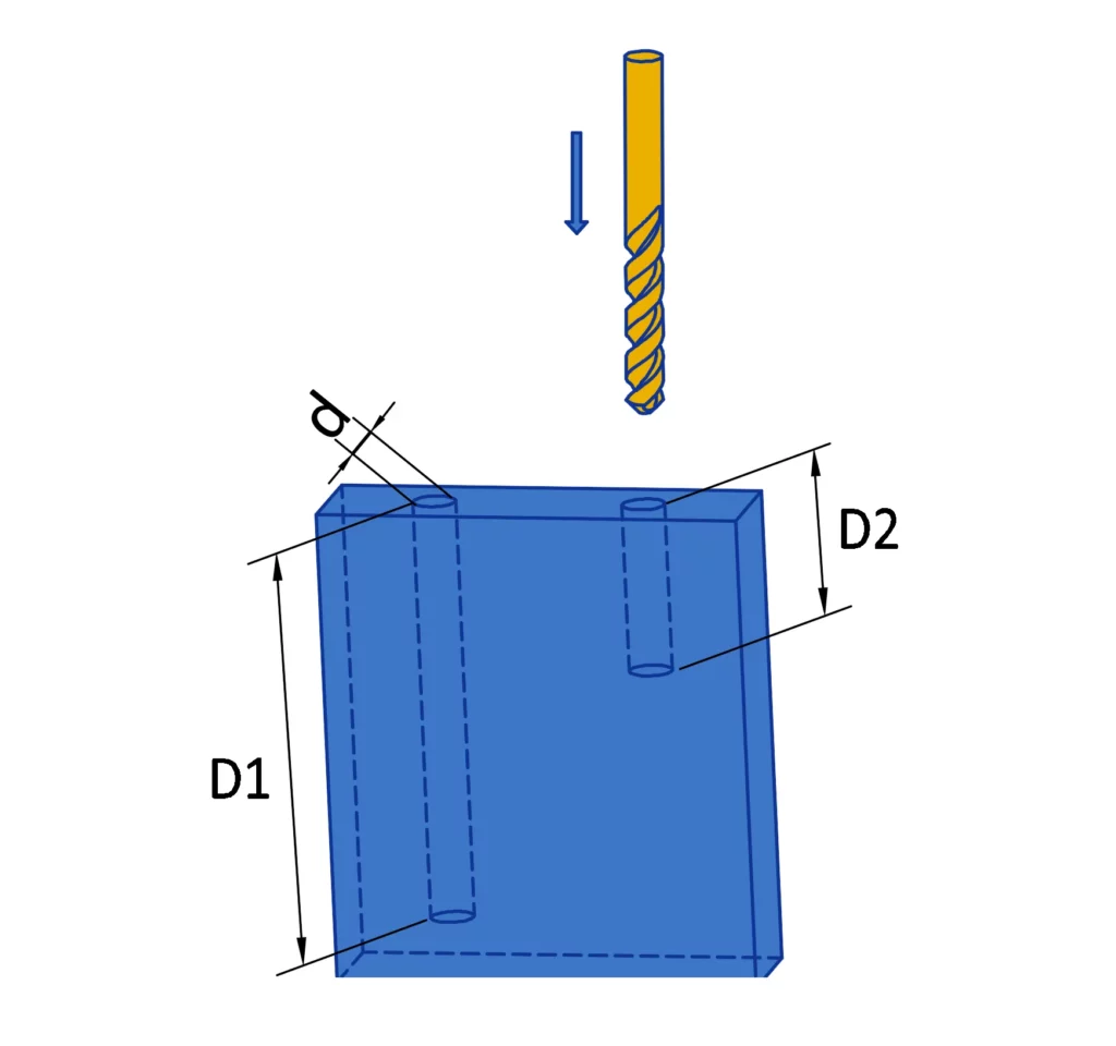
- Standard diameters: Holes are typically machined using a drill bit when possible achieving the best accuracy for diameters under 20mm. Drill sizes generally follow conventional fractions of an inch (e.g., 1/8″, 1/4″) or increments of 0.1mm for holes up to 10mm in diameter, and increments of 0.5mm for larger holes. Non-standard diameters will require machining with an end mill tool and should be treated like cavities (see the previous guideline).
- Hole depths: As the depth of a hole increases, so does the complexity of manufacturing. We recommend maintaining a diameter-to-depth ratio between 1:4 and a maximum of 1:10 for optimal manufacturability.
- Minimum hole diameters: Most CNC services can achieve a minimum diameter of 2.5mm (0.100″). Diameters below this are considered micro-machining and should be avoided unless absolutely necessary.
Internal threads
There are various methods to create threads in a part, such as cut taps, form taps, or thread mills. Each is effective, but designers should consider the following guidelines:
- CAD model preparation: Remove the actual threads from your CAD model, leaving only the pilot diameter. Provide a detailed 2D technical drawing with your 3D model, clearly defining the tapped feature. This should include the thread type, hole size and depth, and any additional details like countersinks or blending treatments.
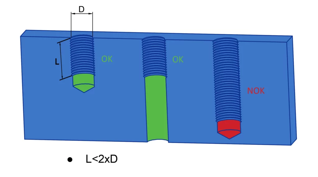
- Thread length: Only thread to the necessary length. For metals, threading beyond twice the hole diameter is typically unnecessary and can increase costs due to specialized tooling requirements for deep threads.
- Thread size selection: Use the largest thread size the design allows to simplify manufacturing. Smaller taps are more prone to breakage, so we recommend M6 as a standard. Threads smaller than M2 pose a higher risk of tool failure.
- Blind holes: Leave an unthreaded length of at least half the hole diameter beyond the thread for tap lead and chip evacuation. A drill relief does not need to be included in the 3D model but should be noted as allowable in the technical drawing.
Standard specifications: Avoid uncommon or custom thread specifications as they may require expensive or specialized tools. We advice to choose right-hand threads for UNC and UNF standards (#2 to 1/2 inch) or metric threads ranging from M2 to M12 for easier manufacturability.
External threads
External threads can be machined using either milling or turning. When the parts meet the conditions for turning, we typically opt for this method. Turning allows external threads to extend along the length of the part, and we often use custom thread tools to define the thread size, depth, and position based on the part’s geometry.
External milled threads, though less common than internal threads, can still be machined effectively. These threads are created by machining one half of the diameter, then rotating the part 180 degrees to machine the opposing threads in the same manner. This method works particularly well for larger or coarse threads, and we can produce high-quality threads up to ½ inch.
As with internal threads, the threads must be removed from the CAD model, and the specifications should be provided in a technical document.
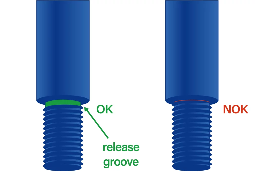
When designing external threads, avoid terminating the threads at a large diameter near or adjacent to a shoulder. This helps maintain thread integrity and facilitates proper machining.
Machined text

Including text and lettering in part designs is generally unnecessary, as it increases machining time and costs. However, if text and lettering are essential for your project, please adhere to the following guidelines:
- For large logos and markings: both concave (engraved) and convex (embossed) shapes are acceptable on the surface.
- For small logos and markings: a concave (engraved) design is preferred. Ensure the depth does not exceed 0.2 mm.
- Font recommendation: if your design software lacks a custom lettering font, use a Sans Serif font with a size of 20 points. This option is cost-effective and widely supported, as many CNC machines have pre-programmed routines for Sans Serif fonts.
Undercuts
Undercuts are features that cannot be machined using standard tools, regardless of how the part is oriented, as the cutting tools cannot access all surfaces. These features are challenging to machine, often requiring specialized tooling or multiple setups, such as a 5-axis machine or EDM process. Optimizing certain undercut clips or slots to eliminate undercut characteristics can help reduce costs and achieve more precise dimensions.
When undercuts are unavoidable, consider the following recommendations:
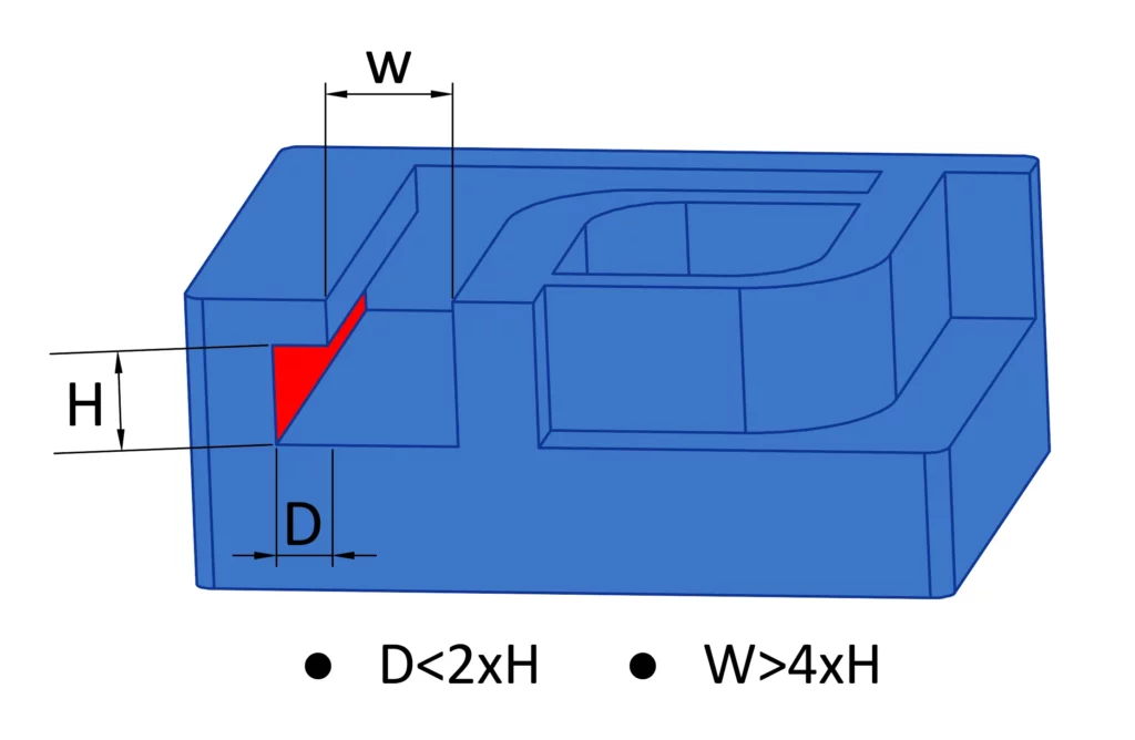
- Design guidelines: use widths in whole millimeter increments or standard inch fractions. Common designs include T-slot undercuts and dovetail undercuts.
- Tool limitations: for non-standard dimensions, custom cutting tools must be created. Standard tools typically have a cutting depth of approximately 2 times their width, limiting the achievable depth.
Choose the right tolerances
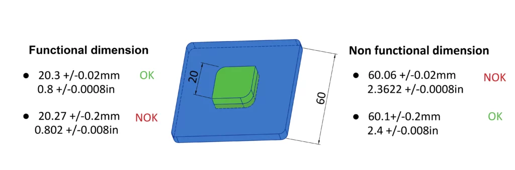
If tolerances are not specified in your design, we will default to standard tolerances, which are sufficient for most non-critical dimensions. This approach helps save both time and money. Keep in mind that tighter tolerances significantly increase costs, as they require additional time for setup, machining, inspection, and other production steps. Specify tight tolerances only when absolutely necessary, and strive for consistency throughout your design to reduce machining time.
Our Recommendations:
- Provide detailed 2D drawings: include tolerances from the beginning to facilitate accurate quoting and ensure the quality of the components.
- Minimize precise dimensions: avoid specifying unnecessary precise dimensions with tight tolerances, as they are more challenging to achieve and add extra costs. Consider the assembly function to reduce the need for such dimensions.
- Use standard dimensions: for non-critical features or sizes, use normal dimensions without tolerances to simplify the process and reduce costs.
Choose the right clearances and avoid errors
A simple yet essential tip, as we frequently encounter errors in assemblies. Generally, parts are designed to fit together or with other components. Therefore, we strongly recommend providing all relevant information about the assembly right from the start. Our technical department will analyze the clearances and potential interferences of the assembled parts based on the data provided and the desired functionality. If necessary, we will propose suitable optimizations while considering the constraints of the CNC machining process.
Cost optimisations for CNC machining
Understanding the factors influencing CNC machining costs is vital to managing expenses. This section explores the factors influencing CNC machining prices and offers strategic insights into reducing the cost of CNC machined parts.
What affects the cost of CNC machining, and how can it be reduced?
In considering the cost aspects of CNC machining, several key factors play a pivotal role:
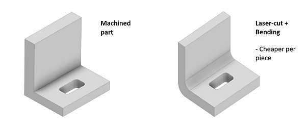
Different CNC machines carry varying operational costs, with some processes inherently more economical than others. For instance, laser cutting is typically the most cost-efficient, followed by CNC turning, 3-axis milling, turn-milling, and then 5-axis milling, each step up in complexity reflecting in the cost. Smart manufacturers and designers aim to utilize machinery that offers the best hourly rate without compromising the part’s integrity. By selecting the appropriate machining process, one can optimize the balance between cost and the complexity of the parts needed.
The type of raw material significantly impacts machining costs. Different materials vary in price, availability, and machining characteristics. For instance, high-performance alloys might be more expensive than common metals, and the availability of certain materials can also influence their cost.
The intricacy of the part or component is crucial in cost determination. Complex designs with intricate features, tight tolerances, and advanced geometries often require specialized tooling and longer machining times, increasing the overall cost.
The duration of machining a part directly affects cost. This includes the cycle time (actual cutting time), setup time (preparation and tool changes), and overall production efficiency. Reducing cycle time and improving setup efficiency can significantly lower costs.
The selection and management of machine tooling are significant cost factors. This encompasses the costs of purchasing, maintaining, and replacing cutting tools. The lifespan of these tools and the time needed for tool changes also impact production efficiency and costs.
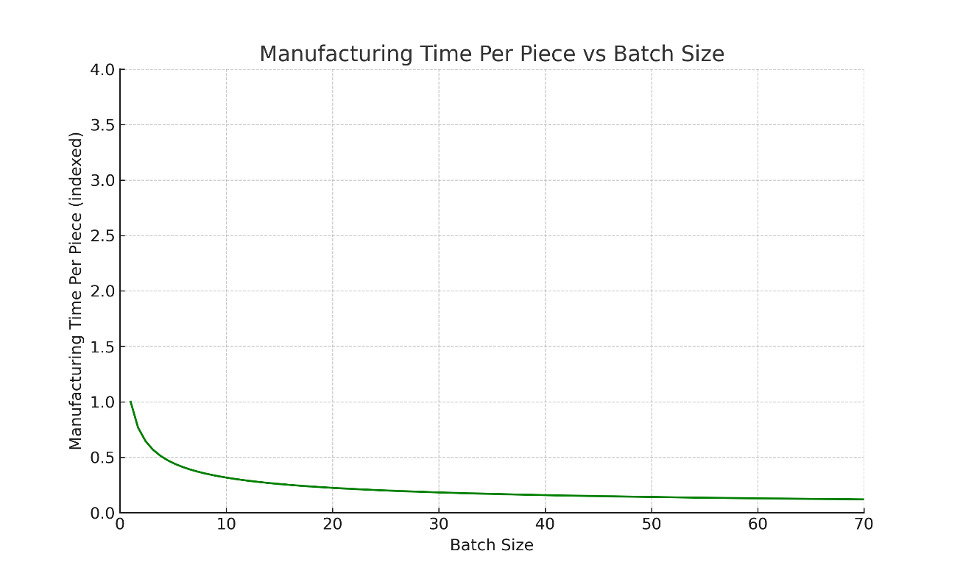
The size of production runs influences costs, with economies of scale playing a role. Larger volumes typically lead to a lower cost per part due to reduced setup time and increased production efficiency. However, smaller batch sizes might incur higher costs per part due to increased setup time.
The expenses for CNC machining engineers and operators contribute significantly to overall costs. This includes wages for skilled personnel proficient in CNC programming, setup, and operation. Labor-intensive operations or complex part requirements may lead to higher labor costs.
Overhead expenses associated with CNC machining, such as facility costs, utilities, administrative expenses, quality control, and inspection, also factor into the total cost calculation. Optimizing these overhead expenses is key to maintaining competitiveness in CNC machining
Costs related to material waste and rework due to errors or specification deviations are crucial. Minimizing scrap through quality control, precision machining techniques, and thorough inspection processes can significantly reduce these costs, lowering overall machining expenses.
By understanding and carefully managing these factors, it’s possible to optimize CNC machining processes for cost-efficiency without compromising on the quality of the machined parts.
Conclusion
This guide has traversed the essentials of CNC machining, from its foundational principles to design intricacies and cost considerations. We’ve explored how a blend of technology and innovation underpins modern manufacturing, the significance of design optimization, and strategies to curtail costs without compromising quality.
At Protolis, we’re committed to delivering top-quality CNC machining services. Our expertise is crafting precision parts tailored to your specifications. For bespoke CNC machining solutions that align with the insights shared in this guide, reach out to us. We’re here to bring your engineering visions to life.