The Protolis guide to compression molding
In this guide, you will find comprehensive instructions for Compression Molding, a widely used method for crafting precise, high-quality rubber components.
Method Type
Jump to current chapter
When to choose compression molding for prototypes and low volume manufacturing
• How to prototype rubber parts
Prototyping rubber parts is essential before compression molding, as rubber behaves in ways CAD cannot fully predict. Physical testing helps catch design issues early and reduces the risk of costly tooling changes. The best prototyping method depends on what you need to validate. Some are ideal for form and fit, while others are ideal for function. Below is a practical comparison of four common approaches, each with its own strengths and tradeoffs.
3D printing: fast iteration, limited accuracy
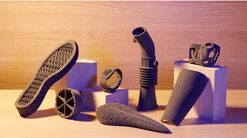
3D printing is usually the first stop in the prototyping process. Common 3D printing technologies include Fused Deposition Modeling (FDM), Stereolithography (SLA), and Selective Laser Sintering (SLS), each offering different strengths in material compatibility, resolution, and durability. With flexible materials like TPU or elastomeric resins, you can produce parts that visually and mechanically resemble rubber, at least to a point. These printed materials typically cover a hardness range from approximately 27 to 95 Shore A, allowing for the simulation of various rubber-like behaviors, from soft and flexible to relatively firm. For compression-molded parts, 3D printing is beneficial for evaluating basic geometry, interface fit, and overall proportions.
The downside is that most printed materials behave quite differently from thermoset or vulcanized rubbers. You will often find that elongation, compression set, and tear resistance do not accurately reflect the actual behavior in production. Still, to quickly explore form and identify apparent design conflicts, it is hard to beat for speed and accessibility.
Explore more information about 3D printing: 3D printing at Protolis
Vacuum casting: closest feel, moderate fidelity
Vacuum casting utilizes a soft silicone mold—typically created from a 3D-printed master—to cast parts in polyurethane or silicone-like materials. While it does not replicate the actual compression molding process, it can come surprisingly close in terms of tactile feel, surface finish, and elasticity, especially when using casting resins that approximate the final shore hardness.
Most vacuum casting materials are available in a hardness range from 30 to 90 Shore A, which covers a broad spectrum of rubber-like behavior, making it a strong choice for simulating the look and feel of production parts, even if the mechanical performance is not an exact match.
This process is particularly useful when you need a small batch of realistic parts for assembly evaluation, field testing, or limited user trials. Please note that there may be slight property deviations compared to compression-molded parts, and some variation between batches may occur due to mold wear or casting conditions.
Explore this section to learn more about vacuum casting: Vacuum casting at Protolis
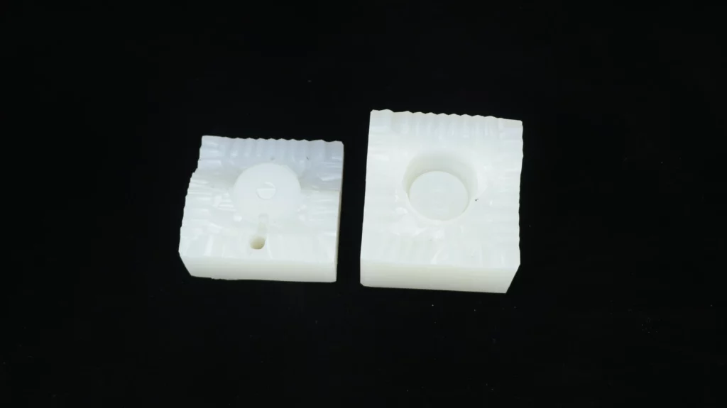
Prototype compression molds
We can develop prototype compression molds much like rapid injection molds. Single-cavity molds are typically machined from aluminum or tool steel. At Protolis, these can normally be produced in approximately two to three weeks, depending on the part size and complexity.
While their primary purpose is early part sampling, single-cavity molds also provide valuable insights for designing full-scale, multi-cavity tools. By isolating one part, you can evaluate geometry, material behavior, and molding conditions with fewer variables. Flow, venting, cure time, and flash are easier to assess, allowing issues to be caught early.
While they do not replicate every production detail, such as thermal gradients or pressure loss, they often reveal enough to guide smarter decisions. Critically, changes to gates, parting lines, or drafts are far simpler at this stage.
At Protolis, we utilize this flexibility to mitigate risk, refine designs, and help our clients scale with fewer surprises and a faster turnaround.
Explore this section to learn more about compression molding: Compression molding service at Protolis
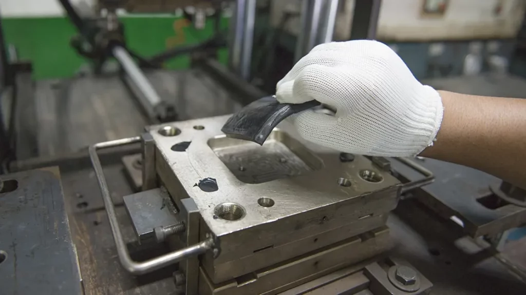
Rapid injection molding: high fidelity, higher cost
If you need prototypes that behave nearly identically to the final production parts, rapid injection molding is typically the closest you will get before full compression tooling. Using aluminum or soft steel molds and actual rubber or TPE materials, you can produce small batches that replicate the final part geometry, tolerances, and mechanical behavior with a high degree of precision.
The tradeoff here is time and cost. Tooling, even for rapid molding, still requires careful design, machining, and iteration. It makes the most sense when functional testing is critical, such as in sealing, fatigue, or regulatory scenarios, and when your budget allows for a more involved prototyping phase. If you are still working out the basic shape or layout decisions, this may be a bit premature.
Explore this section to learn more about rapid injection molding: Injection molding service at Protolis
CNC milling: best for 2D forms and gaskets
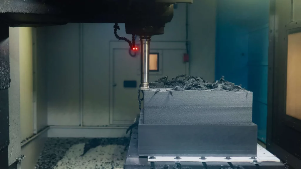
CNC milling can be useful for prototyping solid rubber parts with simple external shapes, such as cylindrical components. The process involves cutting a pre-formed block of material.
The elasticity of rubber makes it difficult to machine. Therefore, milling is only practical for elastomers with a Shore A hardness of 75 or higher. Even then, parts often need support to avoid deflection. A collar placed just above the cutter can help hold the material in place, and freezing the part with liquid nitrogen can temporarily increase its hardness, resulting in cleaner cuts.
Still, even with these tricks, fine detailing is limited, and internal or complex shapes are not feasible. CNC milling has a place in rubber prototyping, but only for firm materials and relatively simple geometries. For softer rubber or more detailed parts, other methods are typically more effective.
Explore this section to learn more about CNC machining: CNC machining at Protolis
Choosing the right method to prototype rubber parts
Prototyping is a critical step in developing rubber parts for compression molding. It helps you validate form, function, and performance before committing to production tooling, saving time, cost, and rework.
At Protolis, we are committed to helping you navigate this process with clarity and confidence. Whether you need guidance on materials, prototyping methods, or the next steps toward molding, our team is here to support you. If you are unsure where to start or would like a second opinion, do not hesitate to reach out. We are ready to help you move forward with a smarter, more reliable path to production.
• When compression molding may not be ideal
While compression molding remains a solid and dependable method for shaping rubber and silicone materials, it is not always the most practical solution for every project. It excels in certain scenarios, particularly with medium to large parts that have relatively simple geometries. Still, there are cases where it can become limiting in terms of speed, consistency, or complexity. Below are some situations where you will generally want to consider alternative production methods.
1. High-volume production
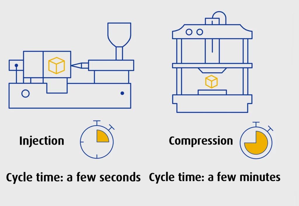
Compression molding tends to be slower than other processes, mainly because each cycle involves manual loading of preforms, followed by extended cure and cooling times. For smaller parts produced at scale, these time costs can add up quickly. The process is reliable, but it does not scale as efficiently when attempting to meet high output demands.
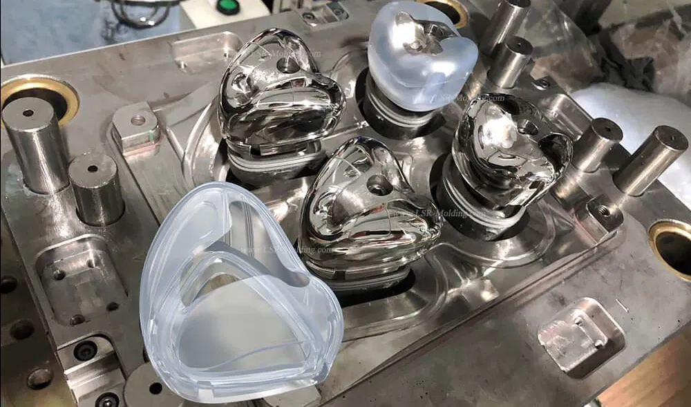
Solution: For high-volume runs, injection molding, particularly with liquid silicone rubber (LSR), offers tighter cycle times and better compatibility with automation.
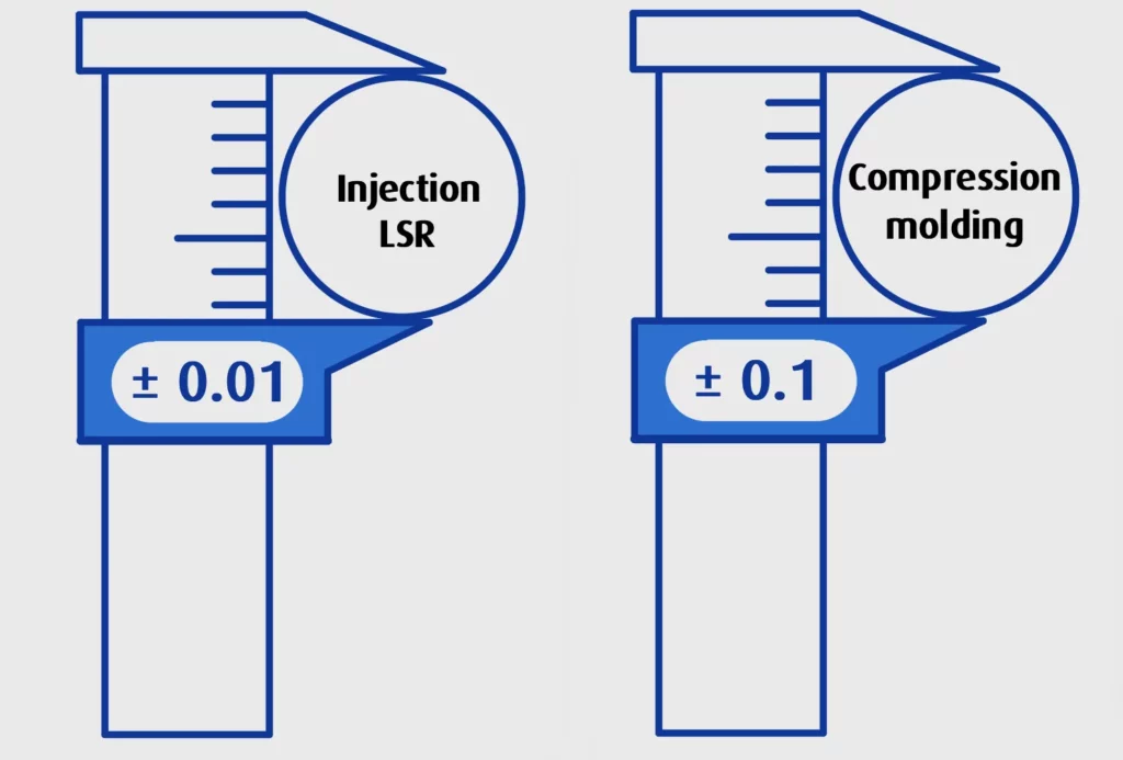
2. Tight tolerances or high-precision parts
Maintaining dimensional accuracy in compression molding can be challenging, especially across multiple cavities. Flow variations, shrinkage, and flash formation all contribute to a degree of variability that can be difficult to control, particularly for parts requiring precision fits or seal integrity.
Solution: In most cases, transfer molding or LSR injection molding is better suited for applications where part-to-part consistency and tight tolerances are critical. For more details on rubber compression part tolerances, refer to this section: Understanding rubber compression molding tolerances
3. Complex or delicate features
Rubber compression molding is generally less suitable for parts requiring fine details or thin-walled features. Because the material must flow under heat and pressure to fill the cavity, it can struggle to reach tight or intricate areas, especially in complex geometries, leading to issues such as air entrapment, incomplete filling, or visible surface flaws.
Solution: LSR injection molding handles complex geometries far more efficiently, delivering cleaner finishes and higher fidelity to the original design.
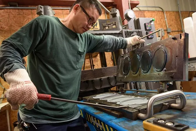
4. Automation and production line integration
Compression molding is often more manual than automated. Operators typically load and unload each mold by hand, and secondary operations, such as deflashing, are usually required. This hands-on approach slows things down and introduces variability.
Solution: When automation is a priority, LSR injection molding provides a more streamlined process, with minimal human intervention and higher throughput.
5. Rapid prototyping and short lead times
Tooling for compression molding is relatively straightforward, but it is not particularly fast to iterate. Changes to the mold or setup can result in downtime, which is undesirable if projects require quick turnarounds or frequent design updates.
Solution: For prototyping or low-volume custom parts, additive manufacturing or vacuum casting are more agile and responsive to design changes. Explore the Protolis Guide to Vacuum casting to learn more about rubber prototyping.
6. Material waste and efficiency
Flash is an inherent byproduct of compression molding. While this can be managed, it often necessitates trimming, which contributes to material waste. In high-precision environments or when working with expensive materials, that waste becomes a significant concern.
Solution: If waste reduction is a priority, injection or transfer molding typically produces cleaner parts with less excess material.
Final thoughts
Compression molding has its place. It is cost-effective for specific applications, relatively simple to set up, and dependable for a range of part sizes. But like any process, it has its limits. At Protolis, we help clients navigate these decisions every day. We are always happy to talk through the pros and cons in the context of your specific application.
Continue your exploration of compression molding in other chapters:
How does compression molding work?
Benefits and limitations of compression molding
Comparison with other technologies