


The assembly of an injection-moulded plastic enclosure should be designed as a complete functional system rather than a collection of individual CAD features.
Before sizing a snap-fit or a locating lip, you should first determine what aligns the two enclosure halves, what locks them together, what carries the mechanical loads, and what compensates for dimensional variation caused by material shrinkage, moulding, and manufacturing tolerances.
Following this DFM approach, locating lips and peripheral interlocking features primarily position the enclosure halves, while snap-fits, screws, or threaded inserts provide mechanical retention. Meanwhile, clearances, chamfers, and draft angles simplify both assembly and part ejection.
Finally, the prototyping stage is equally important because it allows you to verify assembly forces, durability after repeated assembly and disassembly cycles, cosmetic quality, and the actual performance of the selected material.
How to Design the Assembly of an Injection Moulded Plastic Enclosure
Key Takeaways in 30 Seconds
To assemble the two halves of an injection moulded plastic enclosure correctly, four key functions must work together:
- Align the enclosure halves using locating lips, grooves, tabs, or peripheral interlocking features to prevent visible misalignment.
- Secure the assembly with snap-fits, screws, threaded inserts, or other fastening methods suited to the required load, serviceability, and product life cycle.
- Provide the right functional clearances to accommodate material shrinkage, injection moulding tolerances, and assembly variation without creating visible gaps or excessive assembly force.
- Validate the design through prototyping by checking assembly force, part retention, cosmetic quality, ease of disassembly, and durability over repeated assembly and disassembly cycles before investing in production tooling.
The Four Key Functions of Plastic Enclosure Assembly
Align the Enclosure Halves with Locating Features and Peripheral Interlocking
The two enclosure halves should be aligned independently of the fastening system to ensure accurate, repeatable positioning. Locating lips, grooves, tabs, and peripheral interlocking features guide the parts from the start of assembly and prevent visible misalignment. A continuous, well-distributed geometry improves dimensional stability and minimises cosmetic defects along the enclosure’s perimeter.
Secure the Assembly with Snap-fits, Screws, or Other Fastening Systems
Once the enclosure halves are correctly positioned, the fastening system provides long-term mechanical retention. Snap-fits enable quick, tool-free assembly, while screws offer greater load capacity and controlled disassembly. The best fastening method depends on the application’s requirements, including mechanical loads, assembly cycles, and sealing performance, and should be designed to provide reliable retention without overstressing the parts.
Control Clearances and Tolerances to Prevent Assembly Issues
Functional clearances are essential to accommodate variations introduced during injection moulding, including material shrinkage, dimensional tolerances, and process variation. Insufficient clearance increases assembly force, while excessive clearance reduces perceived quality and mechanical stability. Properly defined clearances, together with chamfers and draft angles, help ensure smooth, reliable assembly.
Prototype and Test to Validate Real-World Performance Before Production
Prototyping confirms that the design performs as intended under conditions that closely mirror the final product. It enables engineers to evaluate assembly force, snap-fit performance, part retention, cosmetic quality, ease of disassembly when required, sealing performance, and durability over repeated assembly and disassembly cycles. This step is essential for refining geometry, material selection, or tolerances before production tooling is finalised, thereby reducing risk during the transition to mass production.
Designing Locating Features and Peripheral Interlocking
The design rules for interlocking features and snap-fits are part of DFM best practices for injection moulding. They include minimum wall thickness, draft angles, assembly tolerances, and other key design considerations.
Following these injection moulding design guidelines helps reduce defects such as material shrinkage and snap-fit failures, lowers tooling costs, and accelerates the transition from prototype to production.
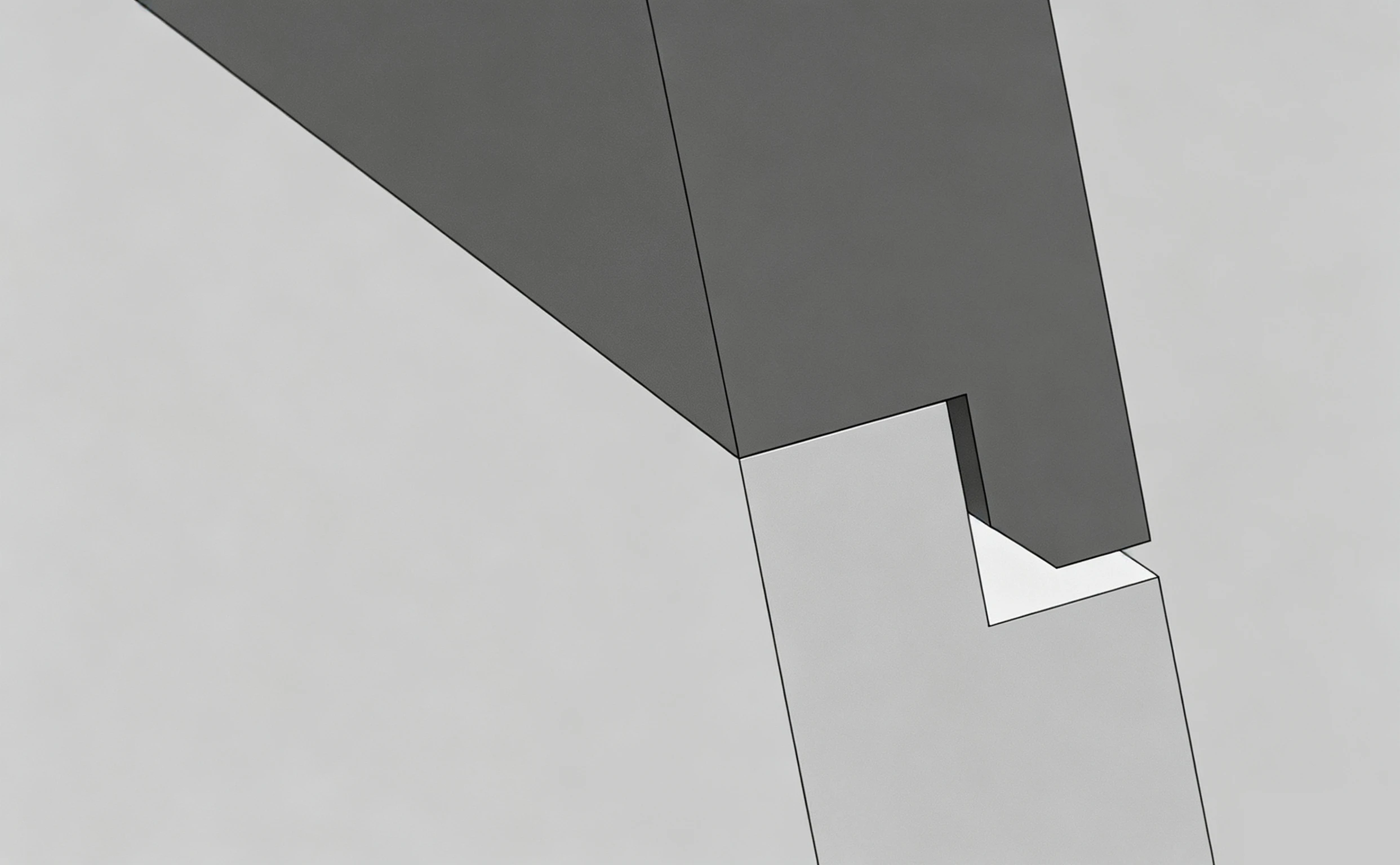
Male Tab and Female Groove
A locating lip is a common structural design feature that ensures accurate positioning and secure alignment between the upper and lower halves of a male-to-female interlocking enclosure.
Male and female locating features are widely used.
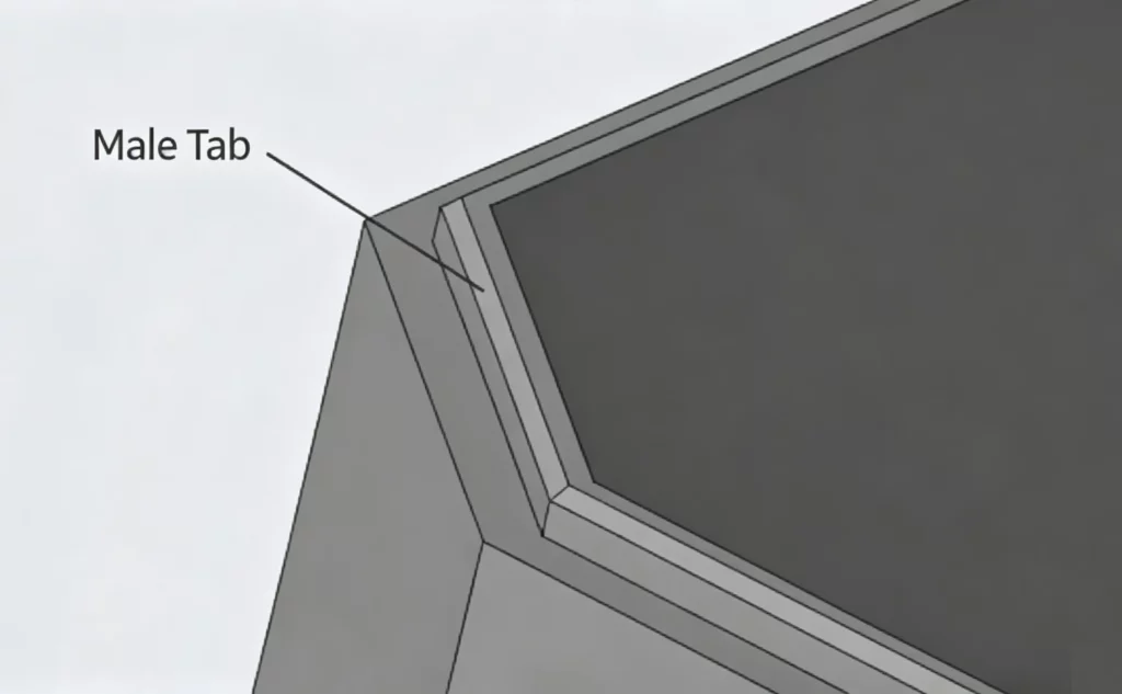
- Tab (male feature): Created by adding material along the inner edge of a plastic part to form a raised locating surface.
- Groove (female feature): Created by removing material from the inner edge to form a recessed locating surface.
Positioning on Thin and Thick Walls
Male locating features are generally positioned on thin-walled parts. Where sufficient space is available, the wall thickness can be increased slightly towards the inside of the enclosure. Female locating features are typically positioned on thicker-walled parts to prevent differences in wall thickness from becoming visible on the exterior surface.
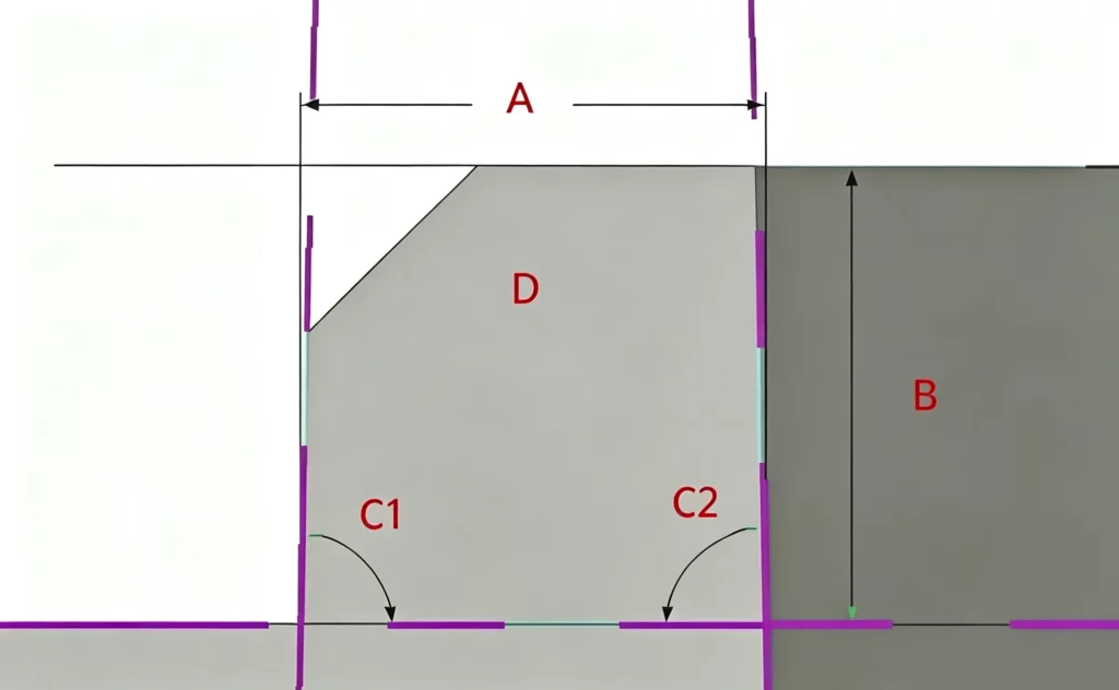
Dimensional Guidelines for Male Locating Features
- A – Width at the base of the male locating lip: 0.60–0.80 mm (0.024–0.031 in)*
- B – Height of the male locating lip: 0.80–1.00 mm (0.0315–0.04 in)*
- C1 and C2 – Draft angles: 2–3 °*
- D – Assembly chamfer size: 0.25–0.30 mm (0.010–0.012 in)*
*Approximate values provided as design guidelines.
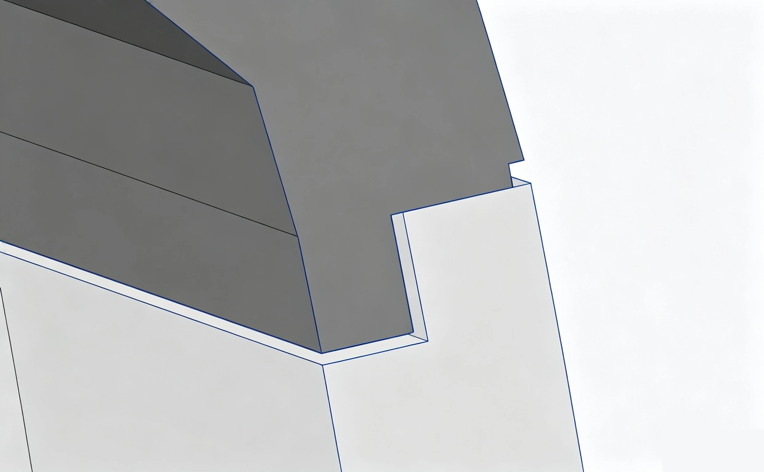
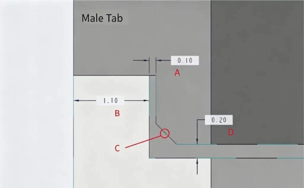
Assembly Clearances and Chamfers
- A – Clearance between the mating surfaces: 0.05–0.10 mm (0.002–0.004 in)*
- C – Chamfer to facilitate assembly.
- D – Clearance around the locating feature: 0.10–0.20 mm (0.004–0.008 in)*. A value of 0.20 mm (0.008 in) is recommended to prevent assembly issues caused by dimensional variation.
*Approximate values provided as design guidelines.
Double Interlocking Features
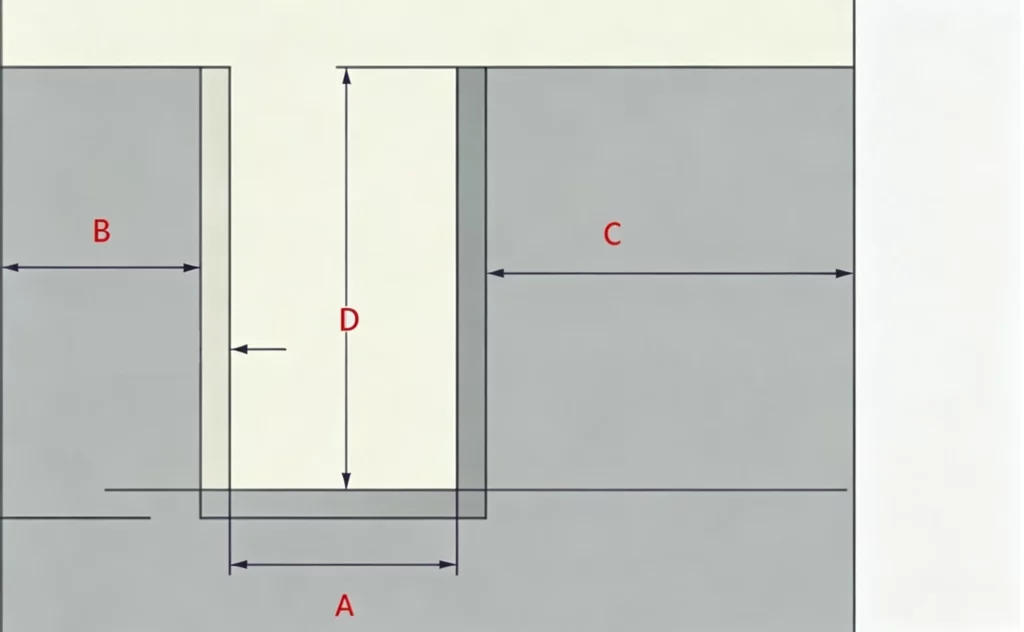
Double grooves improve the alignment of the enclosure halves and help prevent misalignment. They require a wall thickness greater than 2.5 mm (0.098 in).

- A – Width of the male locating lip: 0.80 mm (0.031 in)*
- B – Thickness of the female wall: A minimum of 0.60 mm (0.024 in)* is recommended to improve mouldability.
- C – Width of the external rib on the female locating feature: A value greater than 1.20 mm (0.047 in)* is recommended to prevent visible sink marks or surface defects.
- D – Height of the locating lip: 1.50–2.00 mm (0.06–0.08 in)* is recommended. Excessive height may cause visible surface irregularities on the enclosure’s exterior.
- A 1 ° draft angle is also recommended.
*Approximate values provided as design guidelines.
Retaining Shoulder
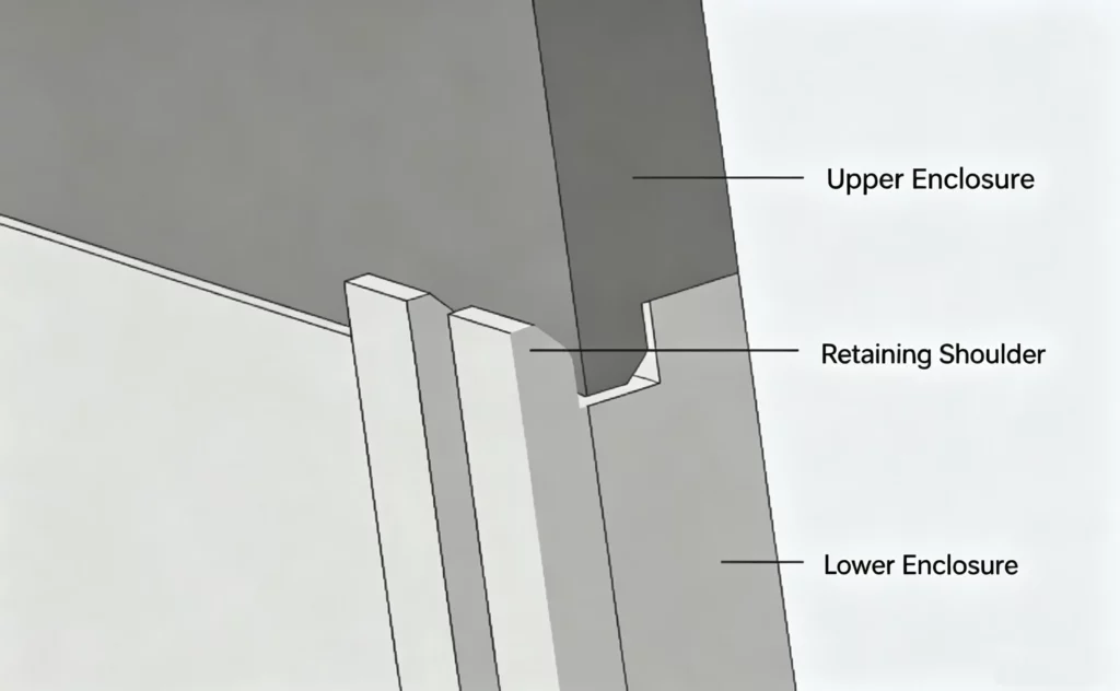
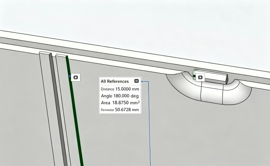
A retaining shoulder is used together with a stop surface. In the example below, it prevents the upper enclosure half from flexing outward and the lower half from contracting inward.
During the design process, the distance between the retaining shoulder and the locking tab should be at least 10 mm (0.4 in). This ensures the locking tab can deflect properly, making the enclosure easier to disassemble.
Designing Snap-fits for Plastic Enclosures
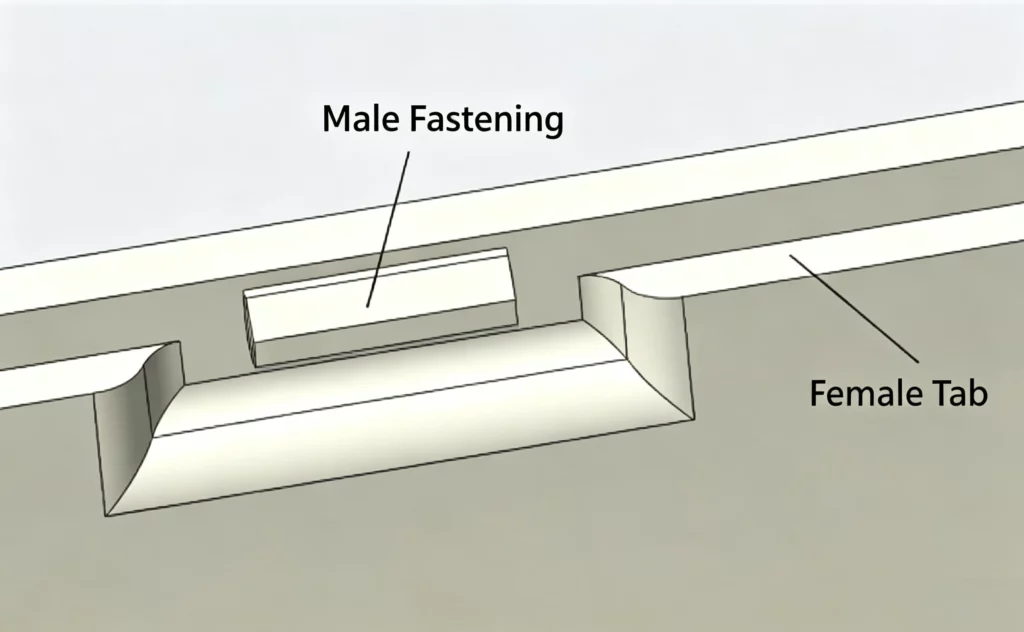
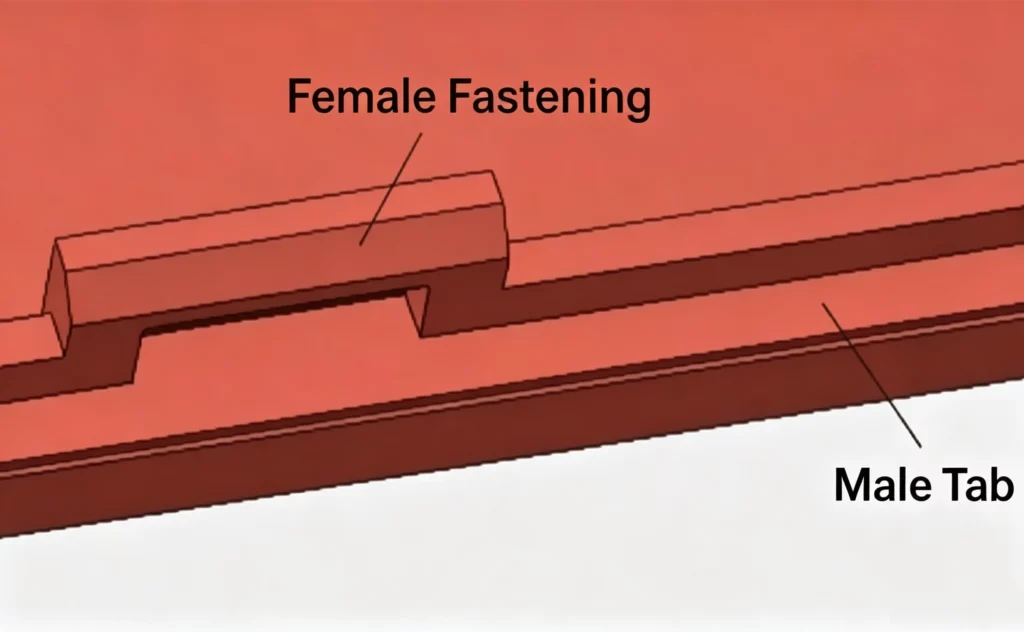
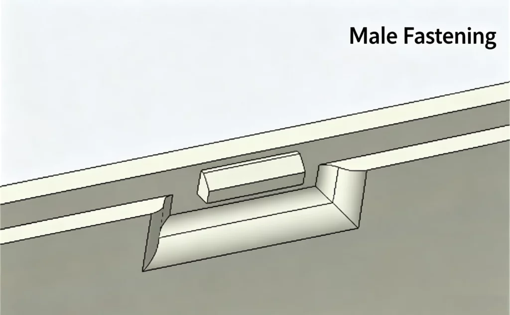
The main advantage of snap-fits is that they enable tool-free assembly and, depending on their geometry, tool-free disassembly.
- The female fastening feature engages with the enclosure half containing the male stop surface.
- The male fastening feature engages with the enclosure containing the female stop surface (the standard fastening configuration).
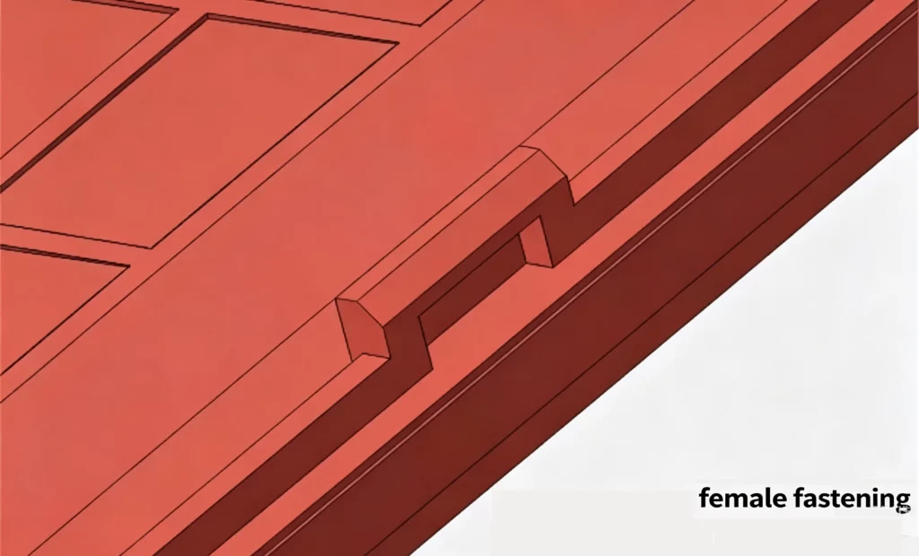
General Snap-fit Geometry
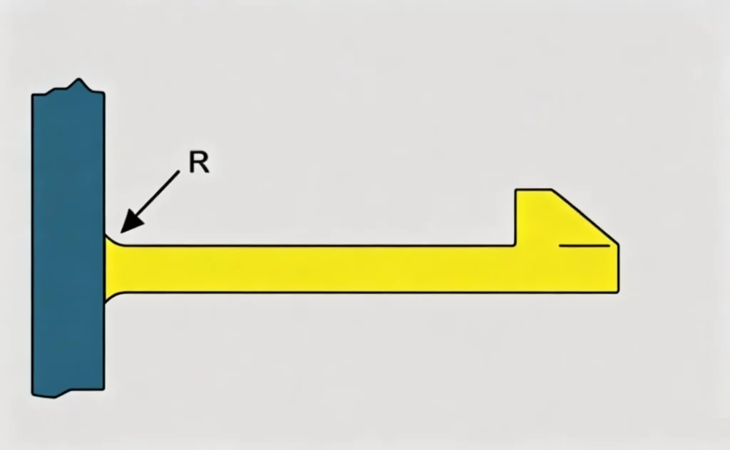
The following are the main design considerations:
- Add a fillet at the base of the clips.
- Snap-fit engagement points must be strong enough to withstand assembly without damage.
- The snap-fit must provide sufficient retention to ensure a secure assembly, especially in sealed enclosures.
- The clips must be able to flex during assembly and disassembly.
The base of a snap-fit is the area subjected to the highest mechanical stress during engagement. A sharp corner concentrates stress and increases the risk of cracking or failure, particularly after repeated assembly and disassembly cycles. For this reason, a smooth fillet should be added between the snap-fit arm and the enclosure wall. This improves stress distribution and extends the service life of the snap-fit while avoiding excessive material build-up that could cause sink marks on the exterior surface.
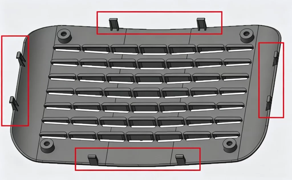
Snap-fit engagement points should be evenly distributed and spaced approximately 30–70 mm (1.2–2.8 in) apart, depending on the part size.
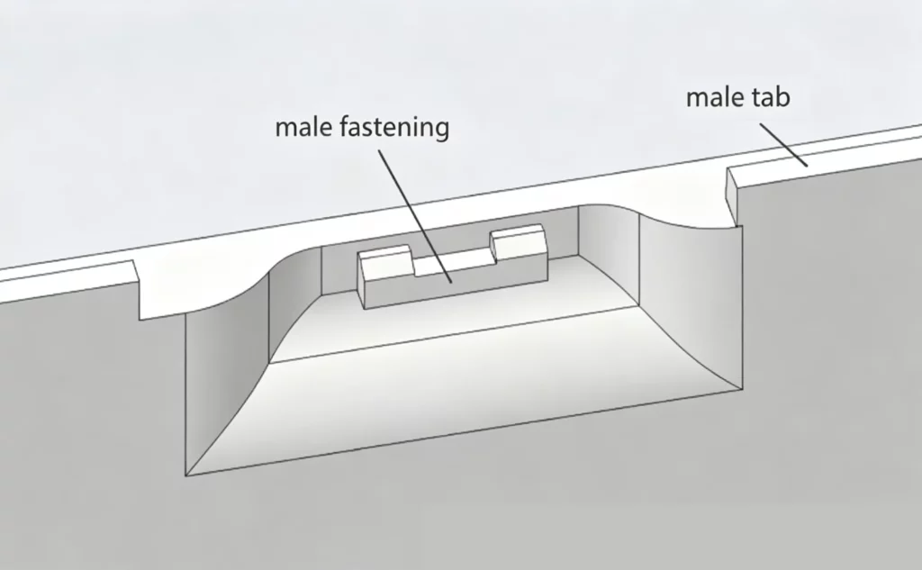
Special Case — Reversed Fastening Configuration
When the female fastening feature is on the same side as the female stop surface, the design is called a reversed fastening configuration.
In this configuration, a 10 mm (0.4 in) relief cut should be provided on both sides of each male stop surface adjacent to the male fastening feature. This allows the fastening point to flex properly and prevents loss of retention during assembly.
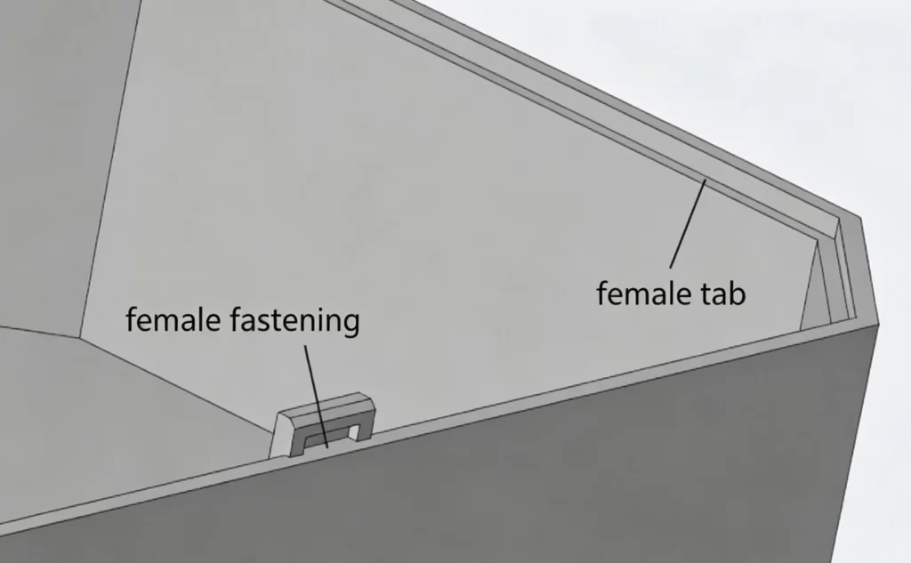
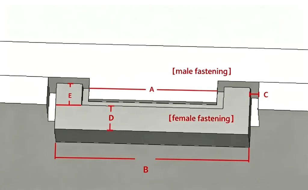
Lateral Dimensions of Snap-fits
- A – Width of the male feature (locking position width): Typically, 2–6 mm (0.08–0.24 in)*, with 4 mm (0.16 in)* the most common value.
- B – Width of the female clip: Equal to A + clearance.
- C – Required assembly clearance at the locking surface: 0.2 mm (0.008 in)*.
- D – Width of the locking surface: A value of 0.6mm (0.024 in)* or greater is recommended. If it is less than 0.6 mm*, the area should be locally relieved, and a reinforcing rib should be added on the back to increase the strength of the fastening feature.
E – Width of the side wall of the female fastening feature: It should provide sufficient strength and is typically 0.8–1.0 mm (0.03–0.04 in)*.
*Approximate values provided as design guidelines.
Clearance and Engagement Depth
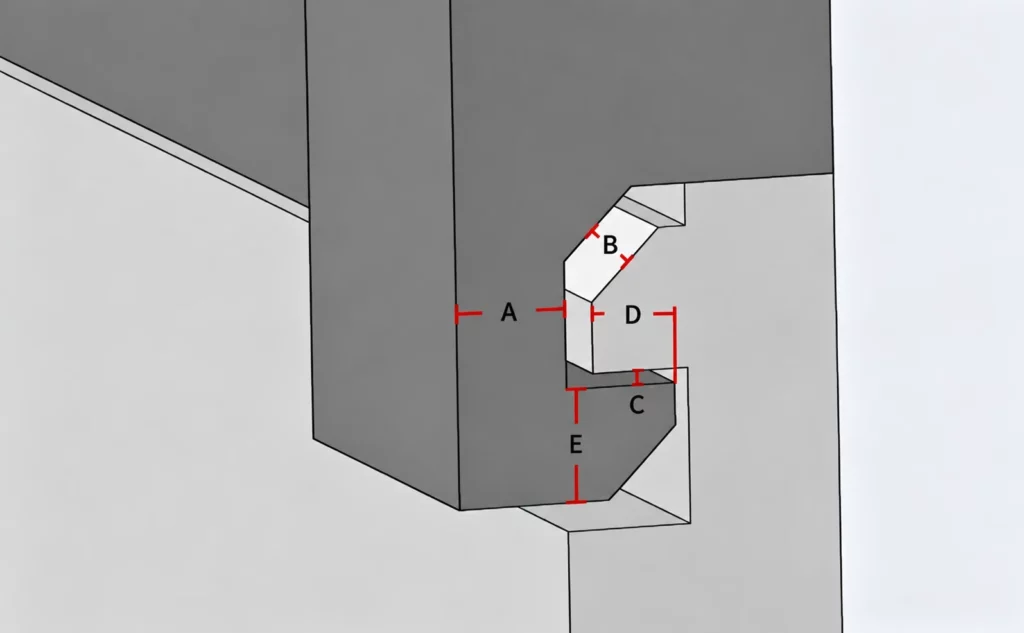
The wall thickness at the tips of the mating male and female features should not be less than 1.0 mm (0.04 in). Under specific design conditions, it may be reduced to 0.8 mm (0.03 in)*.
- A – Thickness at the thinnest section of the female fastening feature: If the section is a visible surface, the wall thickness should be at least 0.8 mm (0.03 in)*.
- B – Clearance at the chamfer required for assembly: Typically, greater than 0.2 mm*.
- C – Clearance at the bearing surface: It should be between 0.05 and 0.10 mm (0.002–0.004 in)* and should not be excessive.
- D – Engagement depth:
- If it is too large, the fastening feature will be difficult to disassemble.
- If it is too small, the snap-fit will not provide adequate retention.
- A value between 0.35 and 0.60 mm (0.014–0.024 in)* is recommended.
- An engagement depth of 0.50 mm (0.020 in)* is commonly used, and an additional 0.30 mm (0.012 in)* of clearance is recommended to provide extra engagement travel.
*Approximate values provided as design guidelines.
Relief Features to Prevent Sink Marks
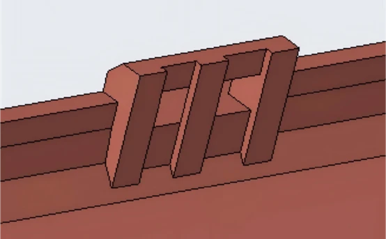
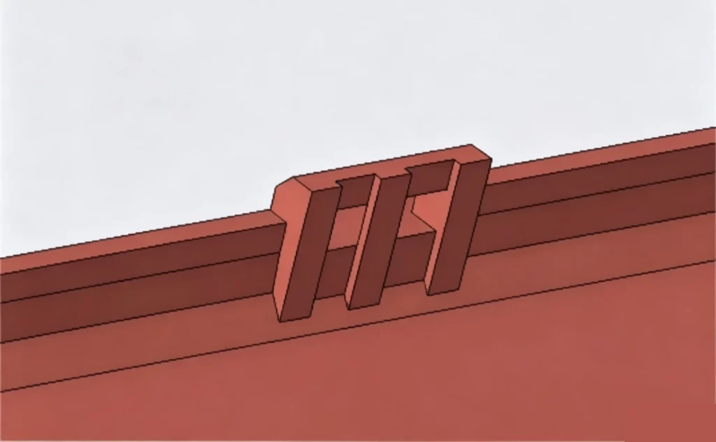
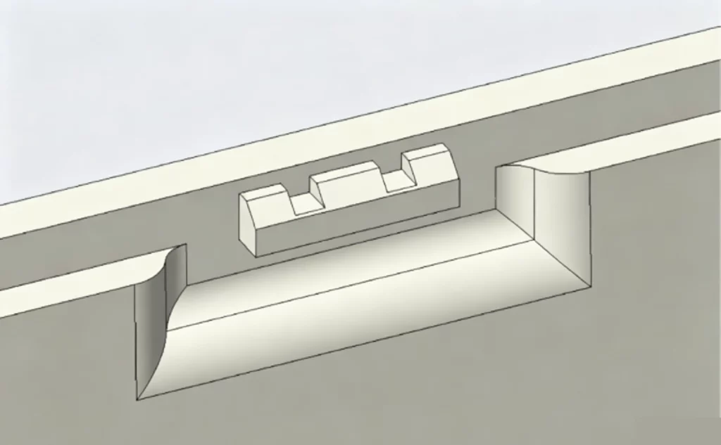
Removing material around the locking features helps prevent excessive wall thickness, which can cause shrinkage and visible sink marks on the surface.
- Male snap-fit: To preserve cosmetic quality, an appropriate relief can be added to the male snap-fit. The remaining wall thickness after material removal should be at least 0.7 mm (0.028 in).
- Back of the female housing: A relieved design may also be used. However, because it reduces structural strength, leaving the female housing completely open is generally not recommended. This design also introduces an undercut that must be accommodated in the mould design and ejection process.
The Most Common Design Mistakes and How to Avoid Them
A snap-fit should not be designed as a simple fastening feature but as a complete mechanical function. It must guide the parts, flex during assembly, lock securely, and maintain its performance over time. The most common design issues typically arise from an imbalance between geometry, functional clearance, tolerances, material selection, and moulding constraints.
Misalignment Between the Two Enclosure Halves
Misalignment usually occurs when snap-fits alone are used to position parts without adequate locating features. Use locating lips, male-to-female locating features, or alignment ribs to clearly separate the alignment function from the locking function.
Visible Gaps
Excessive clearance creates the impression of poor assembly quality and reduces the perceived quality of the enclosure. During the CAD design stage, define functional clearances that account for moulding tolerances, material shrinkage, and tolerance stack-up. Where necessary, add bearing surfaces or stops to limit movement after the snap-fits engage.
Excessive Assembly Force
High snap-fit assembly force is often caused by an insufficient lead-in chamfer, excessive engagement depth, or an overly stiff snap-fit arm. To simplify assembly, provide a gradual lead-in angle, optimise the locking geometry, and verify that the required deflection remains within the elastic capability of the selected material.
Snap-fit Breaks During Initial Assembly
A snap-fit that breaks during the first assembly usually indicates excessive stress concentration caused by a sharp corner at the base of the snap-fit, an undersized cross-section, or excessive deflection. Add a generous fillet at the root of the snap-fit, avoid abrupt wall-thickness transitions, and validate the maximum stress through calculations, simulation, or prototype testing before production tooling begins.
Snap-Fit Does Not Return to Its Original Position
If the snap-fit remains permanently deformed after assembly, it is likely operating beyond its elastic limit or the material lacks sufficient elastic recovery. Reduce the required deflection, increase the flexible length of the snap-fit arm, or select a thermoplastic better suited to repeated deflection while accounting for long-term creep.
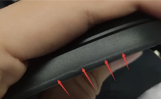
Sink Marks and Surface Defects
Sink marks often appear opposite localised thick sections, especially behind locking features, hooks, or oversized ribs. Maintain the most uniform wall thickness possible, add relief behind the snap-fits, and use thin reinforcing ribs instead of excessive material build-up.
The Enclosure Opens After Repeated Assembly Cycles
If the enclosure opens after repeated assembly and disassembly, the cause may be snap-fit fatigue, material relaxation, or insufficient engagement depth. Design the locking feature with an adequate safety margin, distribute the snap-fits evenly, and verify retention by testing representative prototypes through repeated assembly and disassembly.
Demoulding Difficulties Caused by Undercuts
Snap-fits can easily create undercuts that require side actions, lifters, or removable inserts in the mould. During the design stage, verify the mould opening direction, include draft angles on all vertical surfaces, and simplify the hook geometry whenever the locking function allows.
Choosing the Right Plastic Material for Enclosure Assembly
The choice of material directly affects the assembly’s performance, including the stiffness of the enclosure halves, the flexibility of the snap-fits, and the dimensional stability of the parts. A material that is too rigid may cause the snap-fits to break or require excessive assembly force, while a material that is too flexible may reduce the assembly’s ability to remain securely locked. Selecting a polymer that matches the product requirements is therefore essential.
Examples:
- ABS or PC/ABS for cosmetic enclosures that require a good balance of stiffness and impact resistance.
- POM for components subjected to repeated mechanical motion.
- PBT for applications requiring excellent dimensional stability.
Highly glass-fibre-reinforced grades offer greater stiffness and dimensional stability but are generally less suitable for snap-fits requiring significant elastic deflection.
Material selection should also consider the operating environment, including temperature, humidity, chemical exposure, and long-term performance, to ensure a reliable and durable assembly in real-world conditions.
Which Prototyping Technology Should You Choose to Test a Plastic Snap-fit?
Selecting the right prototyping process is particularly important for snap-fits because their performance depends on the geometry, the material, and the part’s ability to flex without breaking.
Prototyping makes it possible to evaluate:
- Whether the two parts assemble correctly.
- The snap-fit assembly force.
- The reliability of part retention.
- Whether excessive play is present after assembly.
- How easily the assembly can be disassembled.
- Durability after repeated assembly and disassembly cycles.
| Prototyping Technology | Advantages for Testing a Snap-fit | Limitations for Snap-fit Testing |
| 3D Printing | Very fast and cost-effective. Ideal for validating snap-fit location, available space, assembly accessibility, and initial geometry concepts. It also allows multiple design variations to be evaluated quickly. | The mechanical performance rarely matches that of an injection moulded part. Depending on the printing process, parts may be anisotropic, brittle, or overly flexible. Small, thin snap-fits may break more easily than injection moulded ones. |
| Vacuum Casting | A good option for producing a small number of parts with a finish close to production quality. Suitable for evaluating overall assembly, ergonomics, and the general behaviour of the snap-fit in low-volume builds. | The polyurethane resins used do not exactly replicate the behaviour of injection moulded thermoplastics such as ABS, PP, PA, or POM. Fatigue resistance, elastic recovery, and durability over repeated assembly cycles may differ. |
| Plastic CNC Machining | Allows the snap-fit to be manufactured from the same plastic, or a material very close to the final production material. A good choice for evaluating stiffness, deflection, and assembly forces using a representative material. | Some snap-fit geometries are difficult or expensive to machine, particularly undercuts, small internal ribs, and very thin sections. Performance may also differ from injection moulding because the material does not develop the flow orientation created during mould filling. |
| Prototype Injection Moulding | The most representative solution for validating a snap-fit before production. It uses the intended production material and a manufacturing process that closely matches full-scale production. Assembly force, retention strength, repeatability, clearances, material shrinkage, and moulding-related defects can all be evaluated accurately. | More expensive and time-consuming than the other options because it requires a prototype mould. It is therefore best suited to projects with a mature design that needs to be validated under production-like conditions. |
Snap-fit Prototyping: Which Technology Should You Choose?
In practice, 3D printing is often the first step to validate the geometry and to quickly refine the design.
Plastic CNC machining and vacuum casting can then be used to evaluate functional performance with a higher level of realism.
However, for critical snap-fits subjected to high loads or repeated assembly and disassembly cycles, prototype injection moulding remains the most reliable solution. It allows parts to be produced from the final production material or from a material that closely matches it.
Prototype injection moulding also offers a significant advantage: The cost of the mould is generally driven more by the part’s and tooling’s complexity than by the material itself. This means you can produce parts directly in the correct production material, or one very close to it, well before full-scale manufacturing begins.
For snap-fits, this enables earlier validation of the part’s true performance, including flexibility, mechanical strength, assembly force, failure risk, and locking performance.
Protolis: Your Partner for Prototype Manufacturing and Low Volume Production
Protolis supports you throughout the development of snap-fit assemblies, from prototyping through low-volume production.
Our customised manufacturing solutions combine speed and precision to deliver high-quality industrial prototypes worldwide, with short lead times.
Examples:
Injection Moulded Plastic Enclosure for an Electronic Device
→ This plastic enclosure was manufactured by Protolis using rapid injection moulding with prototype tooling. The project focused on validating dimensional tolerances, surface quality, metal insert placement, and assembly precision before moving into production. Multiple materials were evaluated, and repeated assembly trials were conducted to optimise part alignment and fit.
Custom Medical Enclosure for an Advanced Microbiological Testing Device
→ This project involved an ABS enclosure with stainless-steel components, featuring complex internal geometry, undercuts, threaded inserts, and demanding assembly requirements. Critical aspects—including insert alignment, thin walls near the display interface, deformation risk, and the fit of assembled components—demonstrated how the prototype was used to validate geometry, mechanical interfaces, and manufacturability before finalising the design.
FAQ – Assembling an Injection Moulded Plastic Enclosure
What clearance should be provided between the two enclosure halves?
As a starting point, allow 0.05–0.10 mm of clearance at the bearing surfaces and 0.10–0.20 mm around locating lips or stops. A value closer to 0.20 mm is often a safer choice because it helps compensate for material shrinkage and tolerance stack-up.
How do you properly align two plastic enclosure halves?
Alignment should be achieved using dedicated locating features such as locating lips, tabs, grooves, or a peripheral tongue-and-groove design. Snap-fits should not be the sole means of alignment; their primary purpose is to lock the enclosure together. Adequate chamfers and draft angles should also be included to simplify assembly and mould release.
What engagement depth should a plastic snap-fit have?
A typical engagement depth for a plastic snap-fit ranges from 0.35 to 0.60 mm, with 0.50 mm being a common design value. If the engagement is too shallow, retention will be insufficient. If it is too deep, assembly force increases and disassembly becomes more difficult.
How can you prevent a plastic snap-fit from breaking?
Avoid sharp corners at the base of the snap-fit and add a generous fillet to reduce stress concentrations. It is also important to ensure that the required deflection stays within the elastic limits of the selected material. A longer, slightly thinner, or better-optimised snap-fit arm can significantly reduce stress during assembly.
Which plastic material is best for a snap-fit that will be assembled and disassembled repeatedly?
For repeated assembly and disassembly, choose a material that balances fatigue resistance, elastic recovery, mechanical strength, and dimensional stability. POM is well suited for precision mechanical components exposed to wear and cyclic loading, whereas PP provides excellent fatigue resistance but has lower stiffness and dimensional stability.
Which prototyping technology should be used to test a snap-fit enclosure?
3D printing is an excellent first step for validating part size, snap-fit locations, and assembly accessibility. However, to accurately evaluate assembly force, mechanical performance, and material behaviour, prototype injection moulding remains the most representative approach because it produces parts in the final production material or a very similar alternative.