The waterproofing of consumer electronics, measuring instruments, medical devices, and enclosures involves effective protection not only against water but also against dust and sand, and, in some cases, against varying degrees of immersion.
Moreover, waterproofing is not simply an optional design feature. For an enclosure intended to operate outdoors or in humid or dirty environments, proper waterproofing ensures the device’s durability and performance, whereas poor waterproofing can lead to malfunctions and reduce its lifespan.
Depending on the industry, numerous standards exist to classify and evaluate the level of protection provided by mechanical enclosures and electrical housings against the ingress of water, dust, solid objects, and impacts. The best-known is the IEC 60529 standard, whose IP classification system is found on the label of almost all consumer devices.
Rapid prototyping methods are particularly well-suited for testing the waterproofing of designs from the earliest stages of development. This ensures that the product meets all the requirements of the specifications before moving on to mass production.
In this design guide, we will briefly introduce the IEC 60529 standard before taking a closer look at several key design concepts.
Water protection rating (IP code)
The international standard IEC 60529 (formerly IEC 529) establishes a system for classifying the level of protection provided by electrical and mechanical enclosures. This globally recognized standard evaluates the protection these enclosures provide against solid objects and water using a two-digit IP (Ingress Protection) code.
- First digit (0–6): level of protection against solid objects (e.g., 5 = dust-protected)
- Second digit (0–9): level of protection against liquids (e.g., 7 = protected against temporary immersion in water)
Examples:
IP54 indicates an enclosure protected against dust and water splashes.
IP67 means the enclosure is completely dust-tight and can withstand temporary immersion in water.
This standardization of protection levels provides clear information to manufacturers and users, facilitates comparisons between products in international markets, and helps select enclosures suited to each operating environment.
The detailed ratings are presented in Tables 1 and 2.
| Index | Level of protection against solid objects |
| 0 | No protection |
| 1 | Protected against large solid objects (> 50 mm) |
| 2 | Protected against medium-sized solid objects (> 12.5 mm) |
| 3 | Protected against small solid objects (> 2.5 mm) |
| 4 | Protected against very small solid objects (> 1 mm) |
| 5 | Limited dust ingress (dust-protected) |
| 6 | Complete protection against dust ingress (dust-tight) |
| Index | Level of protection against water |
| 0 | No protection |
| 1 | Protected against vertically falling water droplets |
| 2 | Protected against water droplets when the device is tilted up to 15° |
| 3 | Protected against spraying water when the device is tilted up to 60° |
| 4 | Protected against water splashes from all directions |
| 5 | Protected against low-pressure water jets from all directions |
| 6 | Protected against high-pressure water jets and heavy seas |
| 7 | Protected against temporary immersion (typically 1 m / 30 min) |
| 8 | Protected against continuous immersion under specified conditions |
| 9K | Protected against very high-pressure and high-temperature water jets (close-range high-pressure cleaning) |
Special case: when a digit is replaced by an “x”
This means that the level of protection is not specified (most often for dust). For example, an IPx4 rating indicates that the enclosure is protected against water splashes from all directions, without specifying any protection against solid objects.
Compliance testing
In addition to the ingress protection (IP) code, the standard also defines standardized test methods, as illustrated in Table 3 for requirements related to waterproof testing.
Furthermore, many industry-specific standards have been harmonized over the years to incorporate the requirements of IEC 60529 into their products and to establish protection levels tailored to each sector.
Exemple:
This is the case for standards in the IEC 60601 series, which are dedicated to the safety and performance of electro-medical devices.
| Index | Type of exposure | Equipment | Distance / configuration | Flow rate / condition | Duration |
| 0 | — | — | — | — | — |
| 1 | Vertical dripping water | Drip device | ≤ 200 mm | 10.5 mm/min | 10 min |
| 2 | Inclined dripping water (15°) | Drip device | ≤ 200 mm | 30.5 mm/min | 10 min |
| 3 | Spray / rain | Tube or nozzle | 200 mm; 300–500 mm | 0.07 l/min per hole; 10 l/min | ≥ 5–10 min |
| 4 | Splashing water | Tube or nozzle | 200 mm; 300–500 mm | Wider spray arc | ≥ 5–10 min |
| 5 | Water jet | 6.3 mm nozzle | 2.5–3 m | 12.5 l/min | ≥ 3 min |
| 6 | Powerful water jet | 12.5 mm nozzle | 2.5–3 m | 100 l/min | ≥ 3 min |
| 7 | Immersion | Tank | ≥ 1 m depth | Static immersion | 30 min |
| 8 | Continuous immersion | Tank | ≥ 1 m depth¹ | Continuous immersion¹ | ¹ |
| 9K | High-pressure / steam jet | Nozzle | 100–150 mm | 14–16 l/min; 80–100 bar; 80 °C | 30 s per angle; total 2 min |
Table 3 – Waterproof testing requirements according to IEC 60529
Designing a waterproof enclosure: key concepts and pitfalls to avoid
The waterproofing of a device depends on several critical areas. To ensure reliable and durable protection, particular attention must be paid to the following elements:
- Enclosure joints: interfaces between the upper and lower parts of the enclosure
- Buttons: a recurring challenge in waterproof design
- Battery compartments: battery doors and covers
- Other functional openings: sensor and cable pass-throughs
To design waterproof enclosures while addressing these challenges, designers generally rely on a range of proven techniques: sealing compounds, ultrasonic welding, two-shot molding, insert molding, O-rings, etc.
Failures in waterproof designs are generally predictable, as they are most often linked to the following issues:
- Deformation: deformation or warping of plastic parts
- Misalignment: misaligned or uneven sealing surfaces
- Seal compression: too low or too high
- Structural weaknesses: insufficient enclosure rigidity, leading to joint opening
- Uneven pressure: poorly distributed screws causing localized over- or under-compression
- Thread failure: stripped self-tapping threads, resulting in uneven tightening and weak points
It is therefore recommended to examine these aspects carefully to avoid any waterproofing issues in your designs!
Protolis, your partner for prototyping and low-volume production
Rapid prototyping techniques are particularly useful for testing the waterproofing of your designs from the earliest stages of development.
Protolis supports you with turnkey prototyping and low-volume production of custom parts and complex assemblies.
Our tailored solutions combine speed and precision to deliver industrial-grade prototypes worldwide, within short lead times.
Waterproofing of enclosures: technical parameters to consider
As devices requiring maximum waterproofing are generally manufactured using injection molding, this section will mainly focus on plastic injection molding. However, other enclosure manufacturing technologies also exist. On this page, you will also find general design guidelines for the manufacturing of medical enclosures.
1. Controlling plastic deformation and residual stresses
The risk of plastic deformation arises very early in the design phase and can persist throughout the development cycle.
In theory, this deformation can be controlled by:
- Improving gate design
- Optimizing cooling channels
- Adjusting molding parameters
- Adding reinforcing ribs
- Increasing draft angles
In practice, however, controlling these deformations can be complex due to geometric constraints, which often require curved parting lines between the front and rear housings, as well as highly constrained internal layouts leading to uneven wall thicknesses.
These two factors create ideal conditions for warping in injection-molded parts.
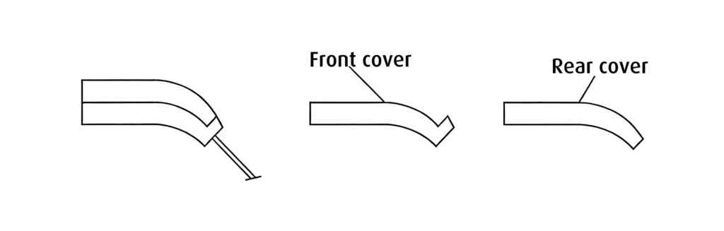
Deformation can therefore be linked to residual stresses from injection molding, as illustrated in Figure 1.
In such cases, simple structural adjustments (adding ribs, increasing draft angles, optimizing the positioning of ejector pins, etc.) may unfortunately prove insufficient to ensure proper waterproofing.
It may also be useful to hold the part in a fixture after molding and to control its cooling in order to relieve internal stresses before the material fully hardens.
Design variant
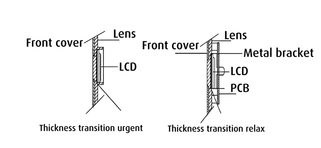
It should also be noted that good waterproofing does not necessarily require an enclosure structure consisting of an upper and lower part.
The example illustrated in Figure 2 presents a design variant. In this case, the outer enclosure surrounds a transparent lens.
If waterproofing is not required, the design shown on the left is acceptable despite a slight risk of deformation.
However, once an O-ring is required, stability becomes essential. The recommended design on the right, therefore, uses a 0.15 mm thick metal cover to enclose the LCD screen and the electronic board, with the assembly screwed directly onto the lens. This approach significantly reduces deformation caused by molding and provides excellent waterproofing.
Test the waterproofing of your plastic enclosures with Protolis
To test waterproofing, the best option is to use rapid injection molding. Rapid injection enables the production of parts with optimal quality, using the appropriate raw material. Protolis can carry out DFM optimizations that are very close to the production version (same gate design, cooling channels, injection parameters, etc.), ensuring a smoother, more predictable transition from prototyping to full-scale production.
2. Alignment of sealing surfaces
Ultrasonic welding is an effective method for ensuring waterproofing, provided the parts’ geometry is suitable.
In ultrasonic welding, the interface between the contacting parts is critical, as it must allow:
- Concentration of vibrational energy
- Controlled initiation of polymer melting
- Controlled flow of the molten material
- Formation of a homogeneous and repeatable weld bead
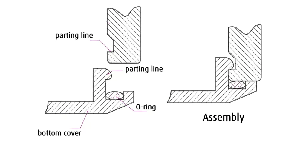
Waterproofing can also be enhanced by using double-weld beads (Figure 3.1), but this approach is reliable only if the enclosure is sufficiently rigid and the weld bead remains continuous.
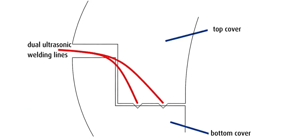
However, there are cases where ultrasonic welding performs poorly and should be avoided. Figure 3.2 provides a good example.
In this case, an O-ring rests on an irregular and curved surface. Once the enclosure is assembled, the sealing line becomes discontinuous and uneven, meaning that waterproofing is not guaranteed. To ensure maximum waterproofing, the sealing surface must lie along a single, continuous line or surface. Any step, break, or discontinuity should be avoided, and complex geometries are risky.
Exemple:
Let’s take a closer look at the sealing line illustrated in section A–A of Figure 3.2. It can be observed that the interface between the upper and lower housings is curved. Water will inevitably penetrate if this line is irregular or interrupted.
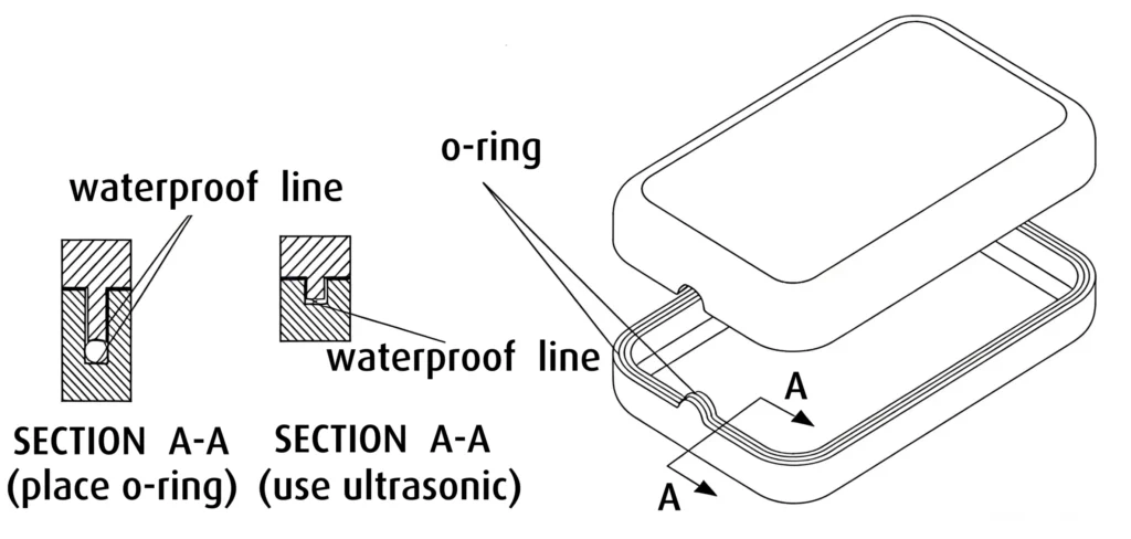
Furthermore, this principle applies equally to circular and square enclosure designs (see Figures 3.3 and 3.4).
Looking for a non-standard O-ring? Protolis can prototype it using vacuum casting or compression molding.
3. Uniform sealing compression
The positioning of screws also plays a key role in achieving effective waterproofing performance.
An uneven distribution of screws leads to uneven compression of the O-ring, creating areas with insufficient sealing or, conversely, excessive stress on the seal:
- Under-compression directly compromises sealing integrity
- Over-compression may push the O-ring beyond its elastic limit. After repeated thermal cycles, an overstressed seal may lose its elasticity
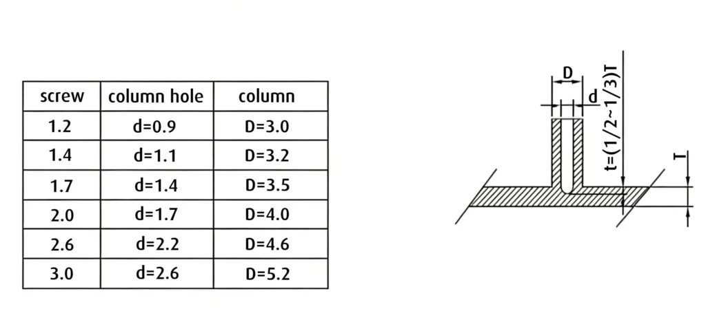
The case of self-tapping screws
Another often overlooked failure mode is thread degradation.
A self-tapping screw creates its own thread in the plastic material. If this thread becomes stripped over time, the assembly‘s local strength decreases, making it impossible to maintain uniform compression of the seal. Water ingress then frequently occurs at these weakened points. Using an appropriate tightening torque is also essential to maintain sealing integrity:
- Excessive tightening can deform the enclosure or crush the O-ring
- Insufficient tightening can leave gaps that allow moisture to penetrate
To avoid this, it is recommended to use a fastening tool that allows precise control of the tightening torque. Applying the same torque to each screw ensures a uniform assembly, preserving both the effectiveness of the seal and the structural integrity of the assembly.
Reinforcing screw bosses, ensuring precise spacing, and controlling tightening torque are not secondary considerations; these parameters are integral to the effectiveness of the sealing system (see Figure 4).
Using prototype injection tooling in the early stages of design accelerates the optimization process, enables iterative testing of screw placement, and ensures a waterproof, robust design, while reducing time-to-market and costs.
To further prevent water ingress at screw interfaces, two methods can be used:
- Install a small sealing gasket directly on the screw
- Design grooves corresponding to the upper and lower screw bosses to securely retain the sealing gasket
These approaches ensure consistent compression and alignment, thereby improving the enclosure’s waterproof integrity.
4. Ensuring structural strength
The rigidity of the assembly is fundamental, regardless of the methods used to enhance waterproofing. Although adding reinforcing ribs is, in theory, the simplest way to increase rigidity, practical constraints often limit their use.
Adding ribs: limitations
Ribs must “coexist” with all the components inside the enclosure: batteries, printed circuit boards (PCBs), displays, connectors, etc. The internal space is therefore usually highly constrained, which limits the options for adding ribs.
When adding ribs is not feasible, wall thickness becomes a critical factor.
Walls that are too thin are prone to bending under mechanical loads, thermal expansion, or the preload applied by screws.
An enclosure that appears robust in CAD simulations but lacks rigidity under real-world conditions will inevitably struggle to maintain its waterproofing performance.
Ultimately, any bending stress can compromise sealing, and no gasket optimization can compensate for insufficient rigidity.
The importance of material selection
Choosing the right material is just as essential to ensure both structural rigidity and long-term waterproofing performance.
The material must not only meet mechanical requirements but also withstand environmental stresses, including temperature variations, chemical exposure, UV radiation (for outdoor enclosures), and physical stresses.
Protolis supports you in material selection
Working with a partner that has expertise across a wide range of materials helps optimize design, both in terms of functionality and durability.
Protolis can assist you in selecting materials that offer the right balance between rigidity, weight, and manufacturability, and provide guidance on advanced solutions tailored to your application. This collaboration is essential for developing a robust, reliable, and waterproof design. The list of materials available for plastic injection molding can be found here.
Sealing of openings
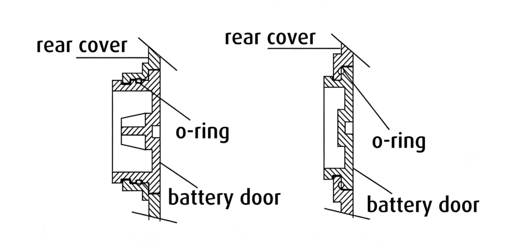
1. Battery compartments
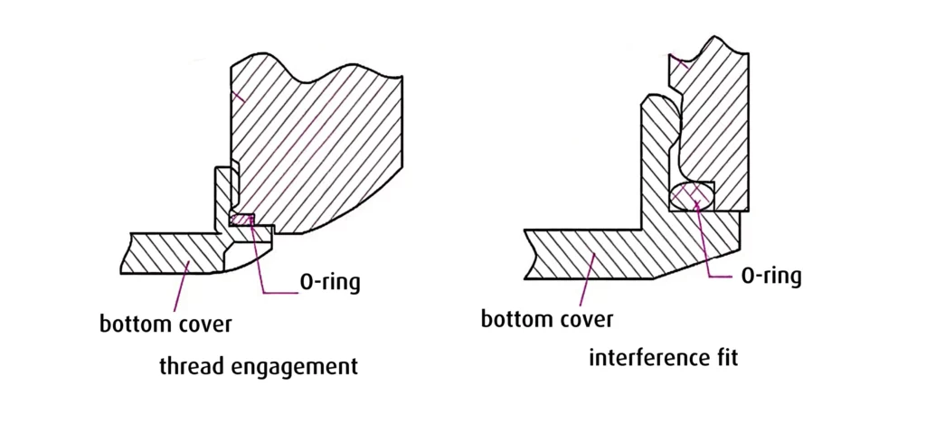
For standard battery compartments (dry cells), it is recommended to implement a sealing structure that ensures consistent compression, ease of use for the end user, and long service life (see Figure 5).
For applications that use button cells, the structural configuration shown in Figure 6 (left) is generally recommended.
If space constraints do not allow this configuration, the solution shown on the right can be used instead.
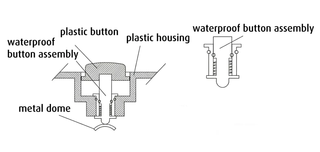
2. Buttons
Buttons are also a critical point in the waterproofing of enclosures.
For compact applications, such as wearable connected devices, the most common waterproof assembly solution is the one illustrated in Figure 7.
This configuration, particularly advantageous when internal space is limited, provides reliable protection that can achieve an IP46 rating, which is sufficient for most common uses.
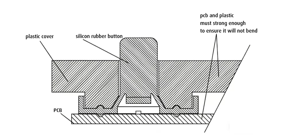
When more space is available, the configuration illustrated in Figure 8 can be considered. This solution uses a silicone keypad, screwed onto a printed circuit board (PCB) and fixed to the upper enclosure.
Button sealing: technical parameters to consider
Particular attention must also be paid to design details in order to ensure long-lasting performance and perfect sealing at the button level (see table):
| Tightening | Rigidity and deformation |
| Alignment of screw bosses Ensure uniform spacing of screw bosses to maintain even tightening pressure. | Deformation management Consider deformation under load of the plastic enclosure, silicone keypad, and PCB. The keypad should absorb most of these deformations to avoid stressing the sealing elements. |
| Reinforcement of screw bosses Use ribs to reinforce screw bosses, improving stability and load distribution. | Wall thickness Avoid overly thin plastic walls, which may compromise structural rigidity and waterproofing. |
| Tightening distribution Provide a sufficient number of screw bosses to securely hold the PCB and prevent any movement. | PCB rigidity Use a rigid PCB material (e.g., FR-4) with a minimum thickness of 1.6 mm to limit bending. |
| Optional stiffening For increased rigidity, consider integrating a steel plate between the PCB and the keypad, especially for applications subject to high mechanical stress. |
3. Cable outlets
An enclosure-type structure generally provides a robust, modular solution to ensure the waterproofing of connection cables before they are connected to the PCB.
This approach consists of first manufacturing sealed subassemblies, which are then enclosed within an outer housing. This method, illustrated in Figure 9, ensures waterproofing while simplifying the assembly process.
How to design waterproofing at the cable level with subassemblies?
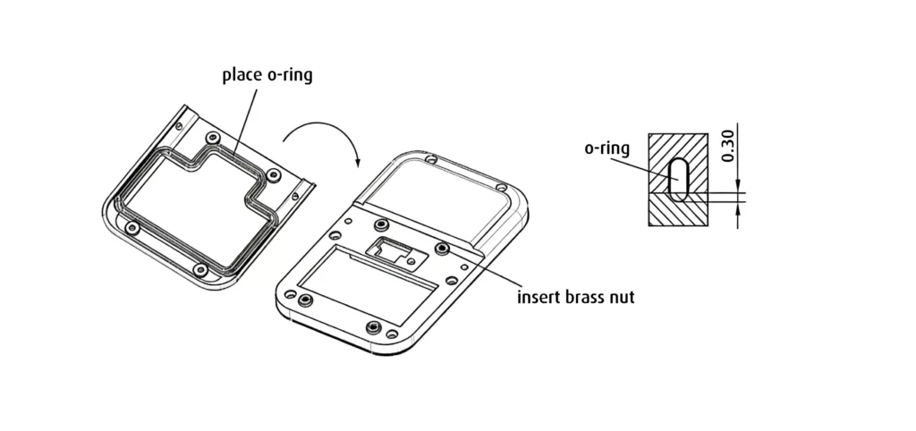
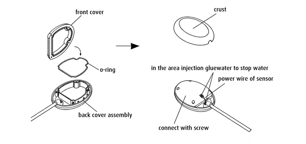
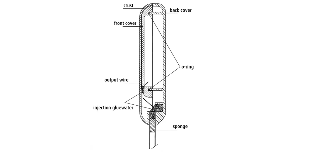
Here are the design steps for an enclosure-type structure ensuring waterproofing at the cable level (see Figure 10):
- Step 1 – Subassembly preparation: The rear enclosure, foam gasket, and adhesive are integrated to form a semi-finished sealed unit.
- Step 2 – Sealing with an O-ring: The front face and rear enclosure are assembled using an O-ring to create a seal between the components.
- Step 3 – Cable integration: Wires are routed through holes drilled in the front face, enabling internal connections while preserving the enclosure’s integrity.
- Step 4 – Sealing the passages: An adhesive is applied to seal the drilled holes, preventing any water ingress at the cable entries.
- Step 5 – Final assembly: The outer cover is securely attached to the semi-finished subassembly using snap-fit clips, ensuring a sealed and durable enclosure.
Application examples:
This enclosure-type structure is widely used in applications such as dive lamps and aquarium lighting, where perfect waterproofing is essential.
Although this method is very effective, other techniques are possible, including two-shot molding and silicone interference compression (radial compression of the silicone seal through interference between the cable, seal, and enclosure). The choice of technique depends on your project specifications.
Choosing the appropriate material is also a determining factor, especially if your product must withstand temperature variations and undergo thermal cycling tests.
Let’s take the design example illustrated in Figure 10:
Polycarbonate (PC) is recommended for the front face and lower enclosure, while the outer cover can be made from either PC or flame-retardant ABS.
PC has a heat deflection temperature of 130–140 °C, a long-term thermal resistance of around 120 °C, and a melting point between 130–160 °C. Since most finished product tests are in the range of 80–90 °C, PC offers a comfortable safety margin without needing to resort to exotic and expensive materials.
Conclusion
The scenarios presented in this article are not exhaustive, as the field of structural waterproof design is complex. Indeed, every project is unique and has its own requirements for waterproofing (IP rating), resistance to environmental stresses, and specific constraints related to costs and manufacturing processes. Therefore, there is no universal “ideal” waterproofing solution. Each design is custom-made and addresses a specific need: yours!
This is where Protolis makes a difference: we listen to your requirements and provide both technical and functional perspectives. We assist you with rapid prototyping for waterproofing, using real parts. The goal is to provide a practical, scalable solution while quickly reducing costs. Do you need help in developing waterproof designs? Would you like a second opinion on an existing design?
Feel free to contact us. Our teams will be happy to help you make the right choices!